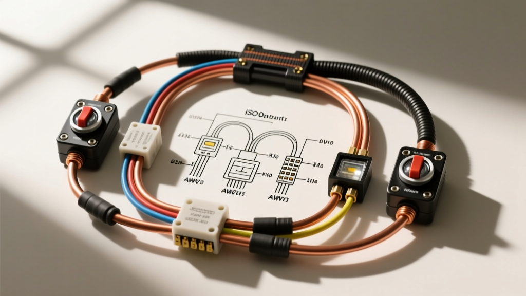
Advanced Topology: The 2-Switch, 2-Light Off-Road Harness
When outfitting heavy-duty trucks like the Ford F-250 Super Duty or Ram 2500 with auxiliary illumination, a standard plug-and-play harness is rarely sufficient. High-draw LED light bars—such as a 50-inch roof-mounted array and a 20-inch bumper-mounted pod—require independent control, robust current handling, and strict isolation from the vehicle’s sensitive Body Control Module (BCM). The wiring diagram 2 switches 2 lights configuration detailed below provides an advanced, OEM-grade blueprint for managing dual high-amperage loads using ISO mini relays, flyback diode protection, and SAE-compliant wiring standards.
This deep dive transcends basic YouTube tutorials. We will cover exact AWG requirements based on SAE J1128 Low Tension Primary Cable standards, precise Deutsch connector crimp specifications, and the critical integration of 1N4007 flyback diodes to prevent inductive kickback from destroying modern upfitter switch circuits.
Component Specifications and AWG Sizing
Before routing a single wire, you must calculate the continuous current draw and voltage drop. A typical 50-inch curved LED light bar draws approximately 14A to 18A at 14.4V, while a pair of 20-inch bumper pods may draw 10A combined. While a single 30A relay might technically handle the combined load, best practices in automotive electrical engineering dictate isolating heavy loads onto independent relays to prevent voltage drop and thermal runaway at the spade terminals.
Wire Gauge Selection Chart (SAE J1128)
| Circuit Application | AWG Size | Max Ampacity (Engine Bay) | Insulation Type |
|---|---|---|---|
| Main Battery Feed (Fuse to Relay Pin 30) | 10 AWG | 55A | Cross-Linked Polyethylene (XLPE) |
| Relay Load Out (Pin 87 to Lights) | 12 AWG | 41A | XLPE / GXL |
| Switch Trigger / Coil Power (Pin 86) | 16 AWG | 18A | PVC / SXL |
| Ground Return (Pin 85 & Light Ground) | 12 AWG (or match 10 AWG main) | 41A | XLPE / GXL |
Using undersized wire in the engine bay, where ambient temperatures routinely exceed 105°C, leads to insulation embrittlement and voltage drop. Always use GXL or SXL cross-linked wire for under-hood routing, as standard PVC primary wire will melt against exhaust manifolds and degrade rapidly.
Schematic Breakdown: Wiring Diagram 2 Switches 2 Lights
This dual-circuit topology utilizes two independent SPST (Single Pole, Single Throw) switches or OEM upfitter auxiliary switches to trigger two separate 40A Bosch-style ISO mini relays. This ensures that Switch A controls Light A (Roof Bar) and Switch B controls Light B (Bumper Pods), with zero cross-talk or shared thermal bottlenecks.
1. The Power Circuit (High Current)
Run a continuous 10 AWG red wire from the positive battery terminal to a centralized marine-grade fuse block (e.g., Blue Sea Systems ST Blade). From the fuse block, route two independent 10 AWG jumper wires to Pin 30 of Relay A and Relay B. Each jumper must be protected by a 30A ATO blade fuse located within 18 inches of the power distribution point. This localized fusing protects the 10 AWG wire in the event of a dead short before it reaches the relay.
2. The Control Circuit (Low Current)
If utilizing OEM upfitter switches (such as the Ford Upfitter S1-S6 bank), these provide a +12V switched output. Route a 16 AWG white wire from Upfitter Switch 1 to Pin 86 of Relay A, and from Upfitter Switch 2 to Pin 86 of Relay B. If using aftermarket dashboard SPST switches, wire the switch input to a fused ignition-switched +12V source (to prevent battery drain), and the switch output to Pin 86.
3. The Ground Circuit
Pin 85 on both relays must be grounded. Do not daisy-chain grounds to random sheet metal. Route a 12 AWG black wire from Pin 85 of both relays to a dedicated, sanded chassis ground point, secured with a stainless steel ring terminal and a star washer to bite through the paint and primer. The negative return for the LED light bars should also be routed to this same star-ground point to prevent ground loops.
ISO Mini Relay Pinout Reference
Standardizing on the ISO 7588-2 mini relay footprint ensures you can source replacements from any Littelfuse or Bosch automotive supplier. Verify the pin stamping on the relay casing, as some cheap imports swap the coil and load pins.
| Pin Number | Designation | Function in 2-Switch 2-Light Setup |
|---|---|---|
| 30 | Common (COM) | High-current +12V input from fused battery feed. |
| 87 | Normally Open (NO) | High-current +12V output to the LED light bar positive. |
| 86 | Coil Power | +12V trigger from Switch A or Switch B. |
| 85 | Coil Ground | Direct connection to chassis star-ground. |
| 87a | Normally Closed (NC) | Unused in this specific auxiliary lighting topology. |
Advanced Protection: Flyback Diodes and BCM Isolation
The most common failure mode in modern truck auxiliary lighting is the destruction of the BCM or Upfitter control module. When the electromagnetic coil inside an ISO relay (between pins 85 and 86) is de-energized, the collapsing magnetic field generates a high-voltage reverse spike (inductive kickback) that can exceed 100V. This spike travels back down the trigger wire and fries the solid-state transistors inside the vehicle’s upfitter module.
The Fix: You must solder a 1N4007 rectifier diode across pins 85 and 86 of each relay. The silver cathode band of the diode must face Pin 86 (the +12V trigger side). This creates a flyback loop that safely dissipates the inductive spike back into the relay coil, completely isolating the vehicle’s sensitive CAN-bus and BCM networks. For a cleaner installation, you can purchase TE Connectivity relay sockets with built-in suppression diodes, eliminating the need for manual soldering.
Termination and Connector Standards
Never use twist-on wire nuts or cheap vinyl electrical tape in an automotive environment. Vibration and thermal cycling will cause them to fail.
- Relay Connections: Use a weather-sealed 5-pin relay socket with integrated silicone gaskets. Crimp the wires using an open-barrel terminal crimping tool (e.g., IWISS or KnowEasy) to ensure a gas-tight mechanical bond.
- Light Bar Connections: Terminate the 12 AWG load wires using Deutsch DT series 2-pin connectors. The DT contact pins require a specific 4-way indent crimp tool. After crimping, insert the pins into the housing until you hear an audible click, then insert the orange secondary wedge lock to prevent the pins from backing out during extreme off-road vibrations.
- Heat Shrink: All soldered joints (such as the flyback diode integration) must be sealed with dual-wall, adhesive-lined marine heat shrink. The inner thermoplastic layer melts and fills voids, preventing moisture ingress and subsequent galvanic corrosion.
Troubleshooting: Voltage Drop and PWM Interference
Even with a flawless wiring diagram 2 switches 2 lights schematic, real-world variables can introduce faults. Use this decision tree to diagnose advanced issues:
Symptom: Light bar flickers or pulses rapidly when switched on.
- Cause A: PWM (Pulse Width Modulation) interference. Many modern OEM upfitter switches use a PWM signal to monitor circuit health or allow dimming. The LED driver inside the light bar interprets this rapid switching as a dimming command, causing a strobe effect.
- Fix: Install a 12V DC relay isolation module or a PWM filter capacitor on the trigger wire before Pin 86 to smooth the signal into a steady DC voltage.
- Cause B: Loose ground connection causing arcing.
- Fix: Measure resistance between the light bar ground pin and the negative battery terminal. It should read less than 0.05 ohms. If higher, sand the chassis ground point and apply dielectric grease.
Symptom: Relay clicks rapidly (chatters) but lights do not illuminate.
- Cause: Severe voltage drop on the trigger circuit. If the 16 AWG trigger wire is too long or has a poor crimp, the voltage reaching Pin 86 drops below the relay’s minimum pull-in voltage (typically 75% of nominal, or ~10.8V). The relay engages, the load draws heavy current, system voltage sags, the relay drops out, voltage recovers, and the cycle repeats.
- Fix: Upgrade the trigger wire to 14 AWG, or use a multimeter to verify that Pin 86 receives a minimum of 11.5V while the switch is engaged and the engine is off.
Final Validation and Testing
Once the harness is routed, secured with UV-resistant cable ties, and loomed in split-corrugated tubing, perform a bench test before connecting the main battery feed. Use a digital multimeter to verify continuity from Pin 87 to the Deutsch connector positive pin. Finally, start the vehicle to engage the alternator (14.2V - 14.4V), toggle Switch A and Switch B independently, and use an infrared thermometer to scan the relay spade terminals and fuse block after 15 minutes of continuous operation. Terminal temperatures should not exceed ambient + 20°C. If they do, re-crimp the connections to eliminate micro-resistances. By adhering strictly to this advanced wiring diagram 2 switches 2 lights protocol, you ensure a bulletproof, OEM-equivalent lighting system capable of surviving the harshest off-road environments.