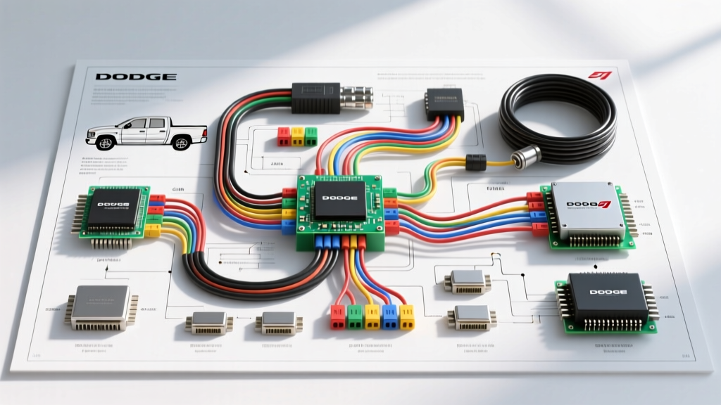
Introduction to Ram 1500 Multiplexed Electrical Architecture
Modern Dodge Ram 1500 trucks utilize a highly complex multiplexed electrical system governed by the Next Generation Controller (NGC) or Global Powertrain Engine Controller (GPEC), depending on the model year. When technicians and DIY mechanics search for a reliable color codes schematic dodge ram 1500 wiring diagram free of charge, they are often met with fragmented, inaccurate, or overly simplified charts that fail to address the intricacies of the Controller Area Network (CAN) bus and the Totally Integrated Power Module (TIPM). This comprehensive troubleshooting guide provides a step-by-step diagnostic flow for tracing PCM circuits, verifying sensor color codes, and resolving communication faults using OEM-level wiring schematics and pinout data.
Required Diagnostic Equipment
Before initiating the troubleshooting flow, ensure you have the following SAE-compliant diagnostic tools:
- Digital Volt-Ohm Meter (DVOM): Must feature a minimum 10-Megohm input impedance to prevent back-feeding and damaging sensitive PCM logic boards.
- Breakout Box / Jumper Harness: Essential for back-probing PCM connectors without piercing wire insulation, which leads to copper oxidation and future green-crust failures.
- Low-Current Clamp Meter: For measuring fuel pump and injector draw without breaking the circuit.
- OBD-II Breakout Box: For monitoring CAN-C and CAN-I bus network integrity at the Data Link Connector (DLC).
Step-by-Step Troubleshooting Flow: U0100 Lost Communication with ECM/PCM
One of the most common electrical faults in the Ram 1500 is the U0100 diagnostic trouble code, indicating that the TIPM or instrument cluster has lost communication with the Powertrain Control Module (PCM). Follow this systematic flow to isolate the fault.
Step 1: Verify Fused B+ and Ignition Power at the PCM
The PCM cannot broadcast on the CAN network without stable voltage. Locate the PCM (typically mounted on the passenger side firewall or inner fender). Identify the main power harness (Connector C1, usually the Black 38-pin connector).
- Test Fused Battery Feed: Back-probe Pin 12 and Pin 13. The wire color code is Red/White (14 AWG). You must read within 0.1V of the main battery voltage (approx. 12.6V key-off).
- Test Ignition Run/Start Feed: Back-probe Pin 24. The wire color code is Dark Green/Orange (18 AWG). Cycle the ignition to the 'RUN' position. Voltage must jump from 0V to 12V+. If missing, trace this circuit back to the TIPM (Totally Integrated Power Module) internal relay bank, a known failure point on 2006-2012 Ram 1500 models.
Step 2: Ground Circuit Integrity and Voltage Drop Testing
A PCM with a floating ground will corrupt sensor data and drop off the CAN bus. Do not simply test for continuity to the battery negative; you must perform a voltage drop test under load.
- Locate the PCM ground pins on Connector C1: Pin 1 and Pin 2. The OEM wire color is Black/Light Blue (14 AWG).
- Set your DVOM to DC Volts. Place the red lead on the battery positive terminal and the black lead on the PCM ground wire (back-probed).
- Crank the engine or activate the main cooling fan to introduce electrical load.
- Specification: The voltage drop must not exceed 0.05V (50mV). A reading higher than 0.10V indicates high resistance in the ground eyelet, usually located on the passenger side cylinder head or inner fender. Clean the eyelet and apply dielectric grease.
Step 3: Analyze CAN-C Bus Topology and Termination Resistance
If power and ground are verified, the issue lies within the high-speed CAN-C network. The PCM communicates with the TIPM, Transmission Control Module (TCM), and ABS module via a twisted-pair data bus.
- Locate the CAN-C pins on PCM Connector C1: Pin 28 (CAN-C High) and Pin 29 (CAN-C Low).
- Wire Colors: Pin 28 is White/Dark Green. Pin 29 is White/Light Blue. Both are 20 AWG (0.5 mm²) twisted pair wires.
- Resistance Test: Disconnect the negative battery cable, then disconnect the PCM C1 connector. Measure resistance between Pin 28 and Pin 29 at the harness side. You should read approximately 60 Ohms. This confirms that the two 120-Ohm terminating resistors (usually located inside the PCM and the TIPM) are functioning in parallel. A reading of 120 Ohms means one module is missing or a wire is broken; a reading of 0 Ohms indicates a dead short between the twisted pair.
- Voltage Test (Active): Reconnect all modules and the battery. With the key 'ON', measure DC voltage to ground. CAN-C High (Pin 28) should pulse around 2.6V, and CAN-C Low (Pin 29) should pulse around 2.4V.
OEM Color Codes Schematic: PCM Connector C1 Pinout Table
Reference the following table for critical NGC PCM Connector C1 (Black) pinouts. This data is derived from OEM service documentation and is essential for accurate schematic tracing.
| Pin | Circuit Function | OEM Wire Color | AWG / mm² | Test Value / Spec |
|---|---|---|---|---|
| 1 | PCM Ground (Z1) | Black/Light Blue | 14 AWG / 2.0 | < 0.05V Drop |
| 2 | PCM Ground (Z2) | Black/Light Blue | 14 AWG / 2.0 | < 0.05V Drop |
| 12 | Fused B+ (A112) | Red/White | 14 AWG / 2.0 | 12.6V (Key Off) |
| 13 | Fused B+ (A113) | Red/White | 14 AWG / 2.0 | 12.6V (Key Off) |
| 24 | Ignition Run/Start (F12) | Dark Green/Orange | 18 AWG / 0.8 | 12V+ (Key On) |
| 28 | CAN-C High (D65) | White/Dark Green | 20 AWG / 0.5 | ~2.6V (Active) |
| 29 | CAN-C Low (D64) | White/Light Blue | 20 AWG / 0.5 | ~2.4V (Active) |
| 34 | 5V Sensor Reference (K5) | Violet/White | 20 AWG / 0.5 | 4.9V - 5.1V |
Advanced Sensor Circuit Tracing: Cam and Crank Sync
If the PCM has power, ground, and network communication, but the engine exhibits a crank-no-start condition, the next step in the troubleshooting flow is verifying the Camshaft Position Sensor (CMP) and Crankshaft Position Sensor (CKP) circuits. The Ram 1500 5.7L Hemi utilizes a dual-tone reluctor ring design.
- 5-Volt Reference Supply: Both sensors share a 5V reference from PCM Pin 34 (Violet/White, 20 AWG). If this circuit shorts to ground (often due to chafing near the alternator bracket), the PCM will protect itself by dropping the 5V bus, causing a no-start and setting codes for the MAP, TPS, and Cam/Crank sensors simultaneously.
- Signal Return: The CKP signal wire is typically Gray/Light Blue, and the CMP signal is Dark Green/Dark Blue. Using an oscilloscope, verify that the CKP generates a 0-5V square wave that transitions cleanly without 'glitches' or 'dropouts' as the harmonic balancer rotates. A missing tooth on the reluctor or excessive runout will cause the PCM to inhibit injector firing.
Real-World Wiring Repair and Splicing Standards
When the schematic tracing reveals a broken wire or chafed harness, proper repair techniques are mandatory to maintain SAE J1128 and OEM waterproofing standards. Never use 'twist-and-tape' methods or standard vinyl electrical tape under the hood.
- Solder Seal Splices: For 18-20 AWG sensor wires (like the CAN bus or 5V reference), use heat-shrink solder-seal connectors. Strip the wire precisely 3/16', twist, and apply heat until the solder ring melts and the adhesive lining extrudes from the ends.
- Crimp Connectors: For 12-14 AWG power and ground feeds, use a ratcheting crimper with nylon-insulated butt connectors. The crimp must pass a 15 lb pull-test.
- Loom and Conduit: After repairing, wrap the harness in split-loom tubing and secure it with Tesa tape (fleece wiring harness tape) to prevent rattling and abrasion against the firewall or valve covers.
TIPM Internal Relay Failures: A Ram 1500 Specific Quirk
No troubleshooting flow for the Ram 1500 is complete without addressing the TIPM. On 2007-2013 models, the internal fuel pump relay (often circuit M25, Dark Green/White wire) is soldered directly to the TIPM logic board. If you have verified 12V at the PCM and ground at the pump, but the fuel pump (drawing 8-12 Amps) receives no power, the TIPM internal micro-relay has likely failed. While a dealership will require a full TIPM replacement and VIN-flashing, advanced technicians can install an external 30-amp automotive relay harness bypass to restore fuel pump operation reliably.
Authoritative References
The diagnostic procedures, wire color codes, and pinout specifications detailed in this guide are cross-referenced with industry-standard documentation:
- SAE International J1939 / J1979 CAN Bus Standards - For network topology and termination resistance parameters.
- Stellantis / Chrysler TechConnect OEM Service Manuals - For NGC PCM pinout data and wire color schematics.
- Haynes Dodge Ram 1500 Repair Manuals - For physical connector locations, ground eyelet routing, and TIPM bypass procedures.