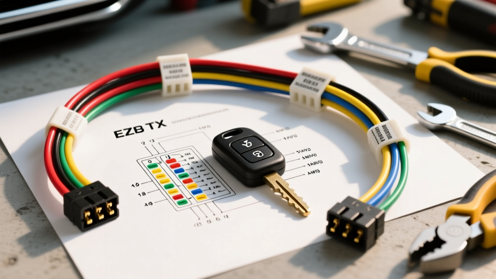
Understanding the EZGO TXT Key Switch Architecture
When sourcing an accurate ezgo txt key switch wiring diagram pdf, technicians and DIY mechanics must account for the specific electrical architecture of their cart. The EZGO TXT platform, spanning from the early 1994 Series models through the 2013 PDS (Precision Drive System) and standard gas variants, relies on the key switch not to carry heavy amperage, but to complete a critical low-current control circuit. This control circuit signals the main high-amperage solenoid to close, thereby bridging the battery pack to the motor controller or starter-generator. Misinterpreting the factory schematic often leads to melted switch housings, dead controllers, or parasitic battery drains.
Unlike standard automotive ignition switches that manage complex CAN-bus networks and immobilizer transponders, the TXT key switch is fundamentally a heavy-duty mechanical single-pole or double-pole throw switch. However, because it operates in harsh, high-vibration, and moisture-prone environments, adhering strictly to the OEM wiring diagrams and SAE wire standards is non-negotiable for long-term reliability.
Interpreting the EZGO TXT Key Switch Wiring Diagram PDF
Factory PDF schematics for the EZGO TXT utilize standardized electrical symbology that can initially confuse those accustomed to modern automotive wiring. In the official EZGO TXT service manuals, a solid black dot at the intersection of two lines indicates a physical splice or junction. Conversely, lines crossing without a dot indicate independent circuits that do not electrically interact.
The key switch is typically represented by a standard SPST (Single Pole, Single Throw) or DPST (Double Pole, Single Throw) symbol, depending on whether the cart is equipped with factory lighting or accessory toggles. The input side of the switch is universally tied to the main battery positive (B+) or a fused 12V/36V/48V accessory bus, while the output side routes directly to the solenoid activation coil or the controller's key-switch input pin. Downloading the correct PDF revision is vital, as the transition from Series-wound motors to SepEx (Separately Excited) PDS motors in the early 2000s fundamentally altered how the key switch interacts with the motor controller's logic board.
Master Specification Table: Pinouts, AWG, and Routing
The following table outlines the standard wire color codes, American Wire Gauge (AWG) requirements, and routing destinations for a standard 36V/48V EZGO TXT Electric key switch circuit. Always verify against your specific serial number's schematic, as aftermarket modifications frequently alter factory color codes.
| Switch Terminal | Function | OEM Wire Color | AWG Size | Destination / Component |
|---|---|---|---|---|
| Terminal 1 (Input) | Main Power In (B+) | Red | 14 AWG | Solenoid Large Post / Fused B+ Bus |
| Terminal 2 (Output) | Solenoid Activation | Black/White Tracer | 14 AWG | Solenoid Small Coil Terminal (S) |
| Terminal 3 (Acc) | Accessory / Lighting Power | Blue | 14 AWG | Voltage Reducer or Light Toggle Switch |
| Chassis Ground | Reference Ground (if req.) | Black | 14 AWG | Main Negative Bus / Controller Ground |
Note: For gas-powered TXT models utilizing a starter-generator, the key switch output routes to the ignition coil and the starter solenoid trigger, utilizing a 12V tap from the voltage reducer rather than full pack voltage.
Electric (PDS/Series) vs. Gas Ignition Circuit Differences
One of the most common errors when reading an ezgo txt key switch wiring diagram pdf is applying an electric schematic to a gas chassis, or vice versa. The electrical demands are vastly different.
Electric Series and PDS Systems
In a 36V Series electric TXT, the key switch carries full pack voltage (36V) to the solenoid coil. When the key is turned to the 'ON' position, 36V travels through the switch, through the micro-switches (F&R switch, throttle V-glide), and into the small terminal of the main solenoid. This creates the electromagnetic field required to pull the heavy copper contactor down, bridging the 6 AWG main battery cables.
In 48V PDS models, the key switch often routes power to the controller's 'Key' input pin. The PDS controller uses this signal to 'wake up' its internal logic board and sequentially close the internal or external solenoid. Sending full 48V directly into a sensitive 12V logic pin without a voltage reducer will instantly destroy the PDS controller.
Gas-Powered TXT Systems
Gas models use the key switch to activate the 12V ignition coil and engage the starter-generator belt drive. Because the TXT gas engine lacks an alternator, it relies on a starter-generator to crank the engine. The key switch completes the 12V circuit from the voltage reducer to the starter solenoid trigger wire. Once the engine fires, releasing the key breaks the starter circuit while maintaining the 12V feed to the ignition coil.
Diagnostic Procedures: Testing the Key Switch Circuit
Before replacing a suspected faulty key switch, perform a rigorous voltage drop test. A failing key switch will often exhibit internal pitting on the copper contacts, leading to high resistance. This resistance generates excessive heat, which can melt the plastic dash bezel and cause intermittent solenoid engagement (the dreaded 'clicking' sound without movement).
- Step 1: Set your Digital Multimeter (DMM) to DC Volts. Ensure the cart is in 'Tow' mode (for PDS) or the batteries are fully charged.
- Step 2: Place the red probe on the input terminal (B+) of the key switch and the black probe on the output terminal.
- Step 3: Turn the key to the 'ON' position. A healthy switch will show a voltage drop of less than 0.1V.
- Step 4: If the DMM reads a voltage drop greater than 0.2V, the internal contacts are degraded. Replace the switch immediately.
- Step 5: Test the solenoid coil resistance. Disconnect the small trigger wires and measure across the solenoid coil terminals. A standard 36V EZGO solenoid coil should read between 10 and 15 ohms. An open loop (OL) indicates a burnt internal coil diode or broken winding.
Connector Crimping, Torque, and SAE Standards
According to SAE J1128 standards for low-tension primary cables, automotive and low-speed vehicle wiring must utilize specific insulation types to resist heat, moisture, and abrasion. When repairing or extending the wires connected to your TXT key switch, always use SAE J1128 compliant GXL or TXL cross-linked polyethylene insulated wire. Standard PVC wire will become brittle and crack under the hood of a gas TXT or inside the exposed dash of an electric model.
For terminal connections, use a ratcheting crimper calibrated for 14 AWG wire to ensure a gas-tight crimp on 1/4-inch female spade connectors. Never use pliers for crimping. Follow the crimp with a 3:1 shrink ratio, adhesive-lined marine heat shrink to prevent moisture ingress and copper oxidation. When securing the ring terminals to the solenoid posts or battery buses, apply a dielectric grease and torque the hardware to exactly 35-45 in-lbs. Over-torquing can strip the soft copper threads on older solenoids, while under-torquing will cause arcing and localized melting.
Sourcing Official PDF Schematics and References
While aftermarket forums are filled with user-drawn schematics, relying on them for complex PDS logic routing is highly discouraged. To obtain the authentic ezgo txt key switch wiring diagram pdf for your specific chassis, you must reference the factory service manuals based on your cart's serial number prefix. Authoritative parts distributors and technical repositories, such as the archives available via Buggies Unlimited EZGO Manuals or the technical libraries at Golf Cart Garage, provide legitimate, high-resolution OEM schematics. These documents include the vital supplemental notes regarding factory splices, ground distribution blocks, and controller pinout matrices that generic diagrams omit.
By treating the key switch circuit with the same technical rigor as a high-voltage EV drivetrain, you ensure that your EZGO TXT delivers reliable, spark-free starts and protects its most expensive downstream components from catastrophic electrical failure.