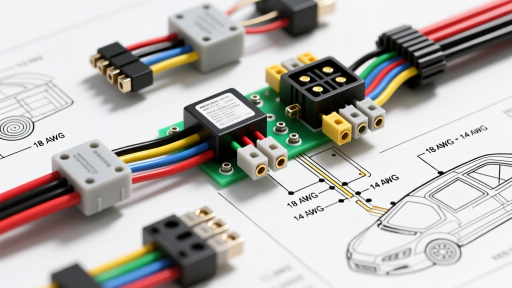
Introduction to Aftermarket Security Schematics
Installing an aftermarket security system requires much more than simply splicing wires together; it demands a precise, methodical understanding of alarm wiring diagrams for cars. Whether you are integrating a Viper, Compustar, or Avital system into a modern CAN bus network or hardwiring an older analog vehicle, misinterpreting a schematic can lead to catastrophic results. These include parasitic battery drains, fried Body Control Modules (BCMs), or a permanently disabled starter circuit. This practical installation guide breaks down universal alarm wiring diagrams for cars, providing the specific wire color codes, American Wire Gauge (AWG) requirements, and relay pinouts necessary for a professional-grade installation.
Decoding Universal Alarm Wiring Diagrams for Cars
Most universal alarm wiring diagrams for cars rely on a standardized color-code palette established by major manufacturers like Directed Electronics (DEI). While specific pinouts on the brain's multi-pin connectors may vary slightly by brand, the main 12-pin power and trigger harness remains remarkably consistent across the industry. Understanding these baseline colors is the first step in reading any car alarm schematic.
| Wire Color | Function | Polarity / Type | Connection Target |
|---|---|---|---|
| Red | Main 12V+ Constant Power | Positive (+) | Battery Positive or Main 12V+ Bus |
| Black | Main System Ground | Negative (-) | Bare Chassis Metal (Ring Terminal) |
| White | Parking Light Output | Positive (+) / Negative (-) | Headlight Switch Harness |
| Green | Door Trigger Input | Positive (+) | Door Pin Switch (Dome Light +) |
| Violet | Door Trigger Input | Negative (-) | Door Pin Switch (Dome Light -) |
| Orange | Accessory Output | Positive (+) 12V | Ignition Harness (ACC Circuit) |
| Yellow | Ignition 1 Output | Positive (+) 12V | Ignition Harness (IGN1 Circuit) |
| Pink | Ignition 2 Output | Positive (+) 12V | Ignition Harness (IGN2 Circuit) |
| Purple | Starter Output | Positive (+) 12V | Ignition Harness (Starter Circuit) |
| Brown | Hood Pin Switch Input | Negative (-) | Aftermarket Hood Pin Switch |
Essential Tools and Wire Gauge (AWG) Specifications
Using the correct wire gauge is critical for safety and system longevity. According to SAE J1128 standards for low-tension primary cables, automotive wire must withstand high under-hood temperatures and resist chemical degradation. Never use household THHN wire or undersized speaker wire for alarm installations. The alarm brain's internal relays and transistors are rated for specific amperages; exceeding these limits due to voltage drop from undersized wiring will melt the harness connector.
| Circuit Type | Recommended AWG | Connector / Termination Method |
|---|---|---|
| Main Power (Red) & Ground (Black) | 10 AWG or 12 AWG | Ring Terminal with Star Washer to Chassis |
| Door Lock Outputs (High Current) | 14 AWG | Splice Connector or Solder + Heat Shrink |
| Ignition / Starter Outputs | 12 AWG or 14 AWG | Solder and Heat Shrink (No T-Taps) |
| Triggers, Sensors, and Siren | 18 AWG | Heat Shrink Butt Connectors |
| CAN Bus Data Lines | 20 AWG to 22 AWG | Solder and Heat Shrink (Maintain Twist) |
Step-by-Step Installation & Wiring Procedure
Step 1: Brain Placement and Main Power/Ground
The physical location of the alarm brain dictates the length of your main power and ground wires. Mount the module high inside the cabin, above the kick panel or under the dash, to prevent water intrusion from floor drains. For the main ground (Black wire), Mobile Electronics Certification Program (MECP) guidelines strictly prohibit grounding to seat belt bolts, thin sheet metal, or painted surfaces. Drill a 5/16-inch hole in a thick structural chassis member, use a self-tapping screw or bolt with a star washer to bite through the paint, and coat the connection in dielectric grease to prevent galvanic corrosion. Use 10 AWG primary wire for both the Red (12V+) and Black (Ground) runs if the distance to the battery or main ground stud exceeds 6 feet.
Step 2: Starter Kill Relay Wiring (Crucial Safety Step)
A starter kill circuit prevents the vehicle from cranking when the alarm is armed. This requires a standard ISO/Bosch-style 5-pin automotive relay. Miswiring this relay is the most common cause of vehicles failing to start after an alarm install. Follow this exact pinout configuration:
- Pin 30 (Common): Connect to the starter motor side of the factory ignition switch harness.
- Pin 87a (Normally Closed): Connect to the ignition switch side of the starter wire.
- Pin 87 (Normally Open): Not used. Cap and tape off securely.
- Pin 86 (Coil Power): Connect to a switched 12V+ ignition source.
- Pin 85 (Coil Ground): Connect to the alarm brain's starter kill output wire (usually Blue or Purple, which provides a ground path only when the system is armed).
Expert Tip: Never wire Pin 86 to constant 12V+. If you do, the relay coil will remain energized continuously, drawing roughly 150mA of current and draining your battery within 48 hours.
Step 3: Data Bus Integration vs. Hardwiring
For vehicles manufactured after 2005, traditional hardwiring of door triggers and ignition wires is largely obsolete and dangerous. Modern vehicles utilize Multiplexed CAN (Controller Area Network) or LIN (Local Interconnect Network) buses. Splicing into a CAN-High or CAN-Low wire with a standard door trigger will cause network faults and illuminate the check engine light. Instead, you must use a data interface module (such as an iDatalink ADS-M3 or Fortin EVO-ALL). As detailed in iDatalink Maestro documentation, these modules connect via a 4-pin or 5-pin data cable (CAN-H, CAN-L, 12V, Ground, and sometimes Ignition). CAN bus wires are typically a twisted pair (e.g., Yellow/Green and Yellow/Blue). When splicing into the factory CAN bus, always strip the insulation carefully, maintain the twist rate as close to the splice point as possible, and use rosin-core solder to ensure a stable 120-ohm termination resistance across the network.
Advanced Wiring: Diode Isolation for Multiplexed Circuits
When installing an alarm in older vehicles (pre-2000) or specific models like older Honda Civics or GM trucks that utilize individual door pin switches wired in parallel to the dome light, you must use diode isolation. If you simply tie the alarm's Violet (Negative Door Trigger) wire to all four door pins, triggering one door will back-feed 12V+ through the other three door switches and into the alarm brain, instantly destroying the internal micro-transistor.
To prevent this, install a 1N4001 or 1N5400 rectifier diode on each individual door trigger wire before they merge into the alarm's Violet wire. The cathode (the end with the painted stripe) must point toward the alarm brain. This allows the negative trigger signal to flow to the brain while blocking any positive voltage from back-feeding the circuit.
Real-World Troubleshooting: Common Wiring Failures
Even with perfect alarm wiring diagrams for cars, real-world variables can introduce faults. Use a Digital Multimeter (DMM) to diagnose these common issues:
- Symptom: Alarm randomly triggers at night, or siren chirps when locking.
Cause: Voltage drop on the door trigger wire, or using a positive trigger (Green) on a negative multiplexed circuit.
Fix: Set your DMM to DC Volts. Measure between the alarm's ground wire and the battery negative terminal while the system is active. If you read more than 0.1V, your ground is insufficient. Re-terminate the ground to bare chassis metal. - Symptom: Starter won't crank, but the alarm is disarmed.
Cause: Starter kill relay wired backward (Pins 87 and 87a swapped) or the alarm brain's kill output is stuck in a closed state due to a shorted wire.
Fix: Pull the relay. Use the DMM in continuity mode to check Pins 30 and 87a. They should have continuity with the relay removed. If they do not, the relay is faulty or miswired. - Symptom: Parasitic battery drain exceeding 50mA while the car is off.
Cause: The alarm brain is not entering sleep mode, often caused by a hood pin switch (Brown wire) that is slightly depressed or misaligned, keeping the circuit hovering between open and closed.
Fix: Adjust the hood pin switch bracket so the plunger is fully compressed when the hood is shut. Verify with a DMM that the Brown wire reads infinite resistance (Open Loop) when the hood is closed.
By strictly adhering to these wiring protocols, AWG specifications, and relay pinouts, you ensure that the vehicle's security system operates reliably without compromising the factory electrical architecture.