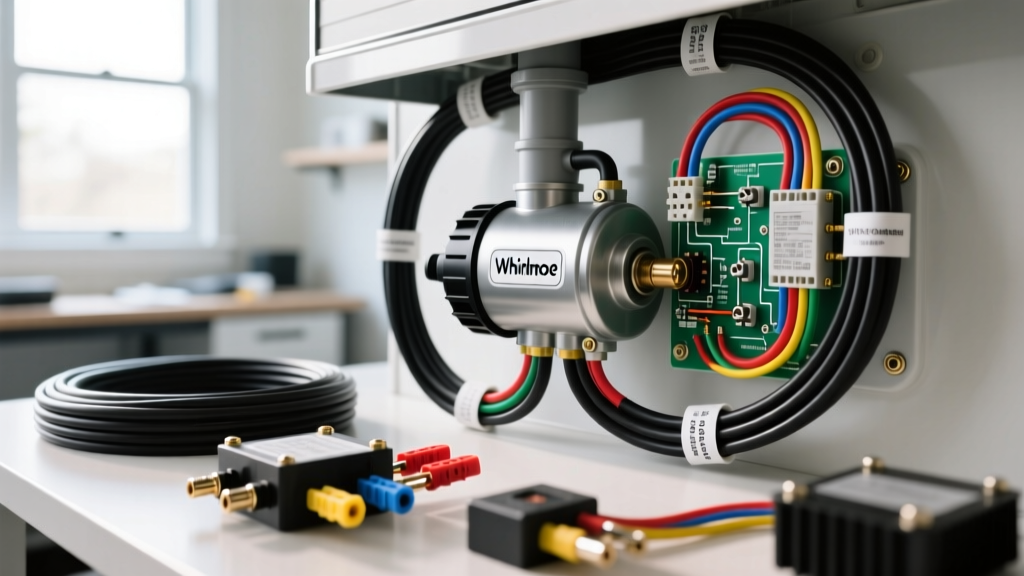
Repurposing Appliance Components for Expedition Vehicles
Expedition vehicles, overlanding rigs, and custom RVs demand robust auxiliary water management systems. Whether you are engineering a high-volume mud-flushing system for a heavy-duty truck or an automated greywater evacuation pump for a camper, standard OEM automotive 12V DC pumps often lack the necessary GPM (gallons per minute) or head pressure. A highly effective, budget-friendly modification favored by advanced fabricators is repurposing a 120V AC drain pump from a household appliance. However, integrating a 120V AC appliance motor into a 12V DC automotive electrical system requires strict adherence to isolation standards, precise relay logic, and a deep understanding of both AC and DC circuit behaviors.
Analyzing the OEM Appliance Circuit
Before modifying any salvaged component, you must understand its original operating parameters. When reverse-engineering these components, consulting the OEM wiring diagram for whirlpool washing machine drain circuits reveals that the pump is typically an 85W to 120W, 120V AC, 60Hz synchronous or induction motor. In models like the Cabrio or Duet series, this pump is driven directly by the Central Control Unit (CCU) via a triac switch. The OEM wiring utilizes 16 AWG or 18 AWG stranded copper with standard 1/4-inch spade connectors.
In a residential appliance, the AC neutral is often bonded to the chassis ground for safety. Critical Automotive Warning: You must never bond the 120V AC neutral to your vehicle's 12V DC chassis ground. Doing so creates a lethal shock hazard, introduces severe ground loops, and will instantly destroy your power inverter. According to ABYC E-11 standards for AC/DC isolation in marine and RV environments, the AC neutral and DC ground must remain completely isolated, relying on a dedicated GFCI breaker for human safety rather than a chassis bond.
AC vs. DC: The Inverter Bridge and LRA
Appliance motors possess high inrush currents, known as Locked Rotor Amperage (LRA). An 85W Whirlpool pump may draw upwards of 400W for the first 200 milliseconds of startup. Therefore, your inverter must be a Pure Sine Wave unit. Running an AC induction motor on a Modified Sine Wave inverter causes harmonic distortion, leading to excessive heat buildup, premature winding failure, and a loud, damaging buzzing noise.
| Parameter | OEM Whirlpool Pump Spec | Automotive Inverter Requirement |
|---|---|---|
| Operating Voltage | 120V AC (60Hz) | 120V AC Pure Sine Wave Output |
| Running Wattage | 85W - 120W | Minimum 400W Continuous Rating |
| Locked Rotor Amperage (LRA) | ~4.5 Amps (Surge) | Minimum 800W Surge Capacity |
| Wire Gauge (OEM vs Mod) | 16 AWG / 18 AWG | 14 AWG SJT Cord (AC Side) |
The 12V DC Control Circuit (Automotive Side)
To control a 120V AC pump from a 12V DC vehicle cab, you cannot simply run high-voltage AC to your dashboard switch. You must use a low-voltage trigger circuit to activate a relay, which in turn powers the inverter's remote-on terminal. This ensures that the inverter only draws parasitic current when the pump is actively needed.
Bosch-Style Relay Pinout Configuration
Utilize a standard 12V, 40A Bosch-style automotive relay housed in a sealed, weatherproof connector. Follow this pinout configuration for the DC trigger side:
- Pin 86 (Coil +): Connect to a momentary ON/OFF toggle switch in the cab. The switch should be fed by an ignition-switched 12V source, protected by an inline 3A ATO fuse.
- Pin 85 (Coil -): Connect to a clean, bare-metal chassis ground. Use a ring terminal and secure with a star washer to bite through paint and powder coating.
- Pin 30 (Input +): Connect to the auxiliary battery bank positive terminal. This must be protected by a 40A ANL fuse located within 18 inches of the battery post, using SAE J1128 compliant 8 AWG primary wire.
- Pin 87 (Output +): Connect to the 'Remote Trigger' or 'REM' terminal on your Pure Sine Wave inverter. (Note: Consult your specific inverter manual, as some require a 12V+ trigger, while others require a ground trigger to Pin 87a).
The 120V AC Load Circuit and GFCI Integration
Once the inverter powers on, it supplies 120V AC to the Whirlpool pump. Because this pump is moving water in a metallic vehicle chassis, a Ground Fault Circuit Interrupter (GFCI) is non-negotiable. Standard automotive breakers do not protect against AC ground faults.
Wiring the AC Side
- Disconnect all power (both 12V DC battery negatives and the inverter's internal capacitors) before touching AC terminals.
- Run 14 AWG 3-conductor SJT cord (Hot, Neutral, Ground) from the inverter's AC output terminals to an inline GFCI receptacle or GFCI breaker box mounted in a dry, accessible area of the rig.
- From the GFCI load side, run the SJT cord to the Whirlpool pump. Because the OEM pump uses spade connectors, crimp on fully insulated, nylon-reinforced female spade terminals using a ratcheting crimper. Apply adhesive-lined marine heat shrink over the crimp barrel to prevent moisture ingress and vibration-induced strand breakage.
- Do not connect the AC Ground (Green) to the vehicle chassis. Connect it only to the inverter's dedicated AC Ground terminal, which internally manages the bond to the inverter chassis according to RV safety codes.
Wire Routing, EMI, and Chassis Pass-Throughs
Routing 120V AC lines alongside 12V DC data lines (like CAN bus or sensor wiring) can induce Electromagnetic Interference (EMI), causing erratic ECU behavior or sensor ghosting. Always route the 120V AC SJT cord on the opposite side of the vehicle chassis from your 12V DC harnesses. If crossing is unavoidable, cross at a strict 90-degree angle.
When passing wires through the firewall or floor pan, use thick rubber grommets. The vibration of an off-road expedition truck will quickly saw through wire insulation if it rests against bare sheet metal. Furthermore, create a 'drip loop' before the wire enters any sealed compartment or pump housing. This ensures that condensation or water running down the cable drips off the bottom of the loop rather than flowing directly into the electrical connections.
Troubleshooting Common Modification Failures
Even with a perfect schematic, real-world vehicle environments introduce unique failure modes. Use this decision tree to diagnose issues:
Symptom: Pump hums loudly but does not spin
- Cause A: Modified Sine Wave Inverter. The harmonic distortion is causing the motor's start capacitor or centrifugal switch to fail to engage. Fix: Upgrade to a Pure Sine Wave inverter.
- Cause B: Voltage drop on the 12V DC side. If your 8 AWG wire run from the battery to the inverter is too long, the inverter's input voltage drops below 11.5V during the pump's LRA surge, triggering the inverter's low-voltage cutoff. Fix: Upgrade the DC feed to 4 AWG wire and ensure clean battery terminals.
Symptom: GFCI trips instantly upon startup
- Cause: Neutral-to-Ground bond conflict. If the salvaged Whirlpool pump still has its internal OEM neutral-to-chassis bonding jumper intact, and you have connected the AC ground wire to the inverter, you have created a direct short across the GFCI sensor. Fix: Open the pump terminal cover, locate the OEM bonding jumper, and remove it to isolate the AC neutral from the pump casing.
Final Torque and Inspection Protocols
Before energizing the system, perform a mechanical and electrical audit. Torque all inverter DC terminal lugs to the manufacturer's specification (typically 4-6 Nm for 8 AWG set-screw terminals). Use a multimeter to verify continuity between the 12V DC ground and the vehicle chassis, and simultaneously verify infinite resistance (open circuit) between the 120V AC neutral and the vehicle chassis. By respecting the boundaries between appliance engineering and automotive electrical standards, your auxiliary water system will provide years of reliable, high-volume service in the harshest off-grid environments.