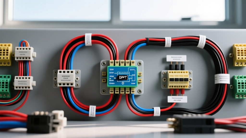
Introduction to Tarp System Electrical Architecture
Operating a commercial dump truck requires securing the load, and an automated tarp system is critical for DOT compliance, aerodynamic efficiency, and roadside safety. When the motor fails to deploy or retract the tarp, the issue almost always traces back to the control harness, switch contacts, or reversing relays. This complete walkthrough of the dump truck tarp switch wiring diagram breaks down the DPDT (Double Pole, Double Throw) switch configuration, the dual-relay motor reversing circuit, and the heavy-duty power distribution required to handle the high inrush currents of 12V DC tarp motors.
Whether you are repairing an OEM Roll-Rite, Shur-Co, or Donovan system, or wiring an aftermarket universal kit, understanding the exact pinouts, AWG requirements, and polarity-swapping logic is essential for a reliable, weatherproof installation. Tarp motors operate in high-vibration, high-moisture environments, meaning standard automotive wiring practices must be upgraded to heavy-duty commercial standards.
Core Components of the Tarp Control Circuit
Before tracing the wires, it is crucial to identify the primary components that make up the typical 12V DC tarp motor control system. Unlike simple on/off circuits, a tarp system requires a polarity-reversing mechanism to change the motor's direction of rotation.
- DPDT Momentary Switch: A Double Pole, Double Throw switch with a center-off position. This switch does not route motor power directly; instead, it routes low-amperage control signals to the relay coils.
- Dual 5-Pin Automotive Relays: Standard Bosch-style 5-pin relays (Pins 30, 85, 86, 87, 87a) are used in pairs to create an H-bridge circuit. This configuration allows the system to swap the positive and negative feeds to the motor terminals depending on which relay is energized.
- 12V DC Permanent Magnet Motor: Typically rated between 30A and 50A under normal load, with stall currents exceeding 80A. These motors rely on polarity reversal to switch between deploy (unroll) and retract (roll-up) functions.
- MEGA or ANL Fusing: High-amperage bolt-down fuses located within 18 inches of the battery positive terminal to protect the main power feed from catastrophic short circuits.
The Polarity Reversal Logic Explained
The most complex aspect of the dump truck tarp switch wiring diagram is the load-side motor reversing circuit. To reverse a DC motor, the positive and negative connections to the motor's brushes must be swapped simultaneously. We achieve this using the Normally Open (NO) and Normally Closed (NC) terminals of two 5-pin relays.
When both relays are at rest (switch in center-off), the motor terminals are connected to ground via the NC (87a) pins, effectively creating a dynamic braking circuit that stops the motor instantly and prevents the tarp from unspooling on the highway. When the switch is toggled to 'Deploy', Relay 1 energizes, sending +12V to Motor Leg A, while Relay 2 remains at rest, providing a ground path to Motor Leg B. Toggling the switch to 'Retract' reverses this state, sending +12V to Motor Leg B and grounding Motor Leg A.
Step-by-Step Wiring Walkthrough
Below is the industry-standard color code and routing guide for a dual-relay tarp system. Always adhere to SAE J1128 standards for primary cable selection in commercial vehicles.
1. Power and Ground Distribution
Begin at the battery. Run a 4 AWG Red wire from the battery positive terminal to a 60A MEGA fuse holder. From the load side of the MEGA fuse, route the 4 AWG wire to a heavy-duty distribution block mounted on the chassis. According to Littelfuse MEGA fuse specifications, this provides adequate headroom for motor inrush currents while protecting against dead shorts.
For the ground distribution, run a 4 AWG Black wire from the battery negative to a dedicated, sanded chassis ground point. Use a 5/16-inch heat-shrink ring terminal and secure it with a Grade 8 bolt and star washer to prevent vibration-induced resistance.
2. Control Circuit (Switch to Relays)
The control circuit handles low amperage and can utilize smaller gauge wire. Tap into an ignition-switched 12V source and run a 14 AWG Red wire through a 15A ATO fuse to the DPDT switch.
- Switch Power In: 14 AWG Red enters the two center terminals (Pins 2 and 5) of the DPDT switch.
- Deploy Signal: When toggled UP, Pin 2 bridges to Pin 1. Run a 14 AWG Yellow wire from Pin 1 to Relay 1, Pin 86 (Coil Positive).
- Retract Signal: When toggled DOWN, Pin 5 bridges to Pin 4. Run a 14 AWG Green wire from Pin 4 to Relay 2, Pin 86 (Coil Positive).
- Coil Grounds: Jumper Relay 1 Pin 85 and Relay 2 Pin 85 together, and run a 14 AWG Black wire to the chassis ground.
3. Motor Reversing Circuit (Load Side)
This is the high-amperage section that requires strict attention to terminal assignments.
- Relay Power Feed: Run 10 AWG Red from the distribution block to Relay 1 Pin 30 and Relay 2 Pin 30.
- Relay Ground Feed: Run 10 AWG Black from the chassis ground to Relay 1 Pin 87a and Relay 2 Pin 87a.
- Motor Leg A: Run 10 AWG Blue from Relay 1 Pin 87 to Motor Terminal 1. Also, run a jumper from Relay 2 Pin 87a to this same Blue wire.
- Motor Leg B: Run 10 AWG White from Relay 2 Pin 87 to Motor Terminal 2. Also, run a jumper from Relay 1 Pin 87a to this same White wire.
Wire Gauge, Fusing, and Connector Specification Chart
| Circuit Segment | Wire Gauge (AWG) | Protection / Fuse | Recommended Connector Type |
|---|---|---|---|
| Battery to Distribution Block | 4 AWG SXL | 60A MEGA / ANL | 5/16" Heat-Shrink Ring |
| Distribution to Relay Pins 30 | 10 AWG SXL | Inline 30A ATO | Heavy-Duty Spade / Relay Harness |
| Relay Pins 87/87a to Motor | 10 AWG SXL | N/A (Protected by Main) | Deutsch DT 4-Pin (Motor Pigtail) |
| Ignition to DPDT Switch | 14 AWG GXL | 15A ATO | Amp Superseal 1.5 Series |
| Switch to Relay Coils (86) | 14 AWG GXL | N/A | Sealed Splice / Relay Harness |
Upgrading to Continuous-Duty Solenoids
While standard 40A Bosch-style relays work for lighter aluminum tarp systems, heavy-duty steel roll-tarp systems or older motors with worn brushes can pull sustained currents that melt standard relay contacts. For high-amperage applications, we recommend upgrading the dual-relay setup to continuous-duty solenoids, such as those manufactured by Trombetta.
When using Trombetta DC power contactors, the wiring logic remains identical, but the physical terminals change. The heavy copper studs handle the motor load (equivalent to Pins 30, 87, and 87a), while the smaller spade terminals handle the switch control (equivalent to Pins 85 and 86). Solenoids also feature superior internal arc suppression, which is critical when breaking the inductive load of a spinning DC motor.
Advanced Multimeter Diagnostics and Failure Modes
When a dump truck tarp motor fails to operate, do not immediately replace the motor. Use a digital multimeter (DMM) to isolate the failure point using these professional diagnostic steps:
1. Voltage Drop Testing Across the Switch
Set your DMM to DC Volts. Place the red probe on the switch power input and the black probe on the switch output leg (Yellow or Green) while holding the switch in the engaged position. A healthy switch will show a voltage drop of less than 0.1V. If you read 0.5V or higher, the internal copper contacts are carbon-fouled or pitted from arcing, and the switch must be replaced.
2. Relay Coil Resistance Verification
Disconnect the relay harness. Set the DMM to Ohms and measure across Pins 85 and 86. A standard 12V automotive relay coil should read between 70 and 90 ohms. If the meter reads 'OL' (Open Loop), the internal coil wire has snapped due to vibration or thermal fatigue. If it reads near 0 ohms, the coil is shorted internally.
3. Motor Amp Draw and Brush Inspection
Use an inductive DC clamp meter around the 4 AWG main power feed. Activate the tarp. A healthy motor should draw between 30A and 45A while rolling the tarp. If the amp draw spikes to 80A+ and the motor stalls or hums, the issue is rarely electrical wiring; it is typically mechanical binding in the tarp arms, or the motor's internal carbon brushes have worn down to the springs, causing severe commutator resistance.
Weatherproofing the Installation
The cab-to-chassis harness transition is the most common failure point in dump truck tarp wiring. Always use a Deutsch DT 4-pin connector with silicone rear seals and wedgelocks to join the cab switch harness to the chassis motor harness. Wrap all chassis-side loom in split-loom tubing and secure it with UV-resistant zip ties every 6 inches. Finally, apply dielectric grease to all relay spade terminals before seating them into their sockets to prevent galvanic corrosion from road salt and brine.