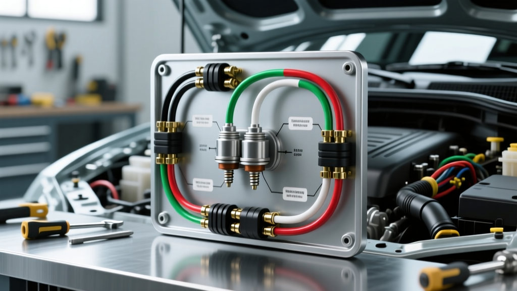
Understanding the 4-Wire Oxygen Sensor Architecture
When diagnosing drivability issues, fuel trim anomalies, or emissions failures, referencing an accurate 4 wire oxygen sensor wiring diagram is the critical first step. Unlike older 1-wire or 2-wire sensors that relied on the engine block for grounding, modern 4-wire heated oxygen sensors (HO2S) utilize a dedicated signal ground circuit. This isolated ground path prevents voltage drops across the engine block from skewing the millivolt signal sent to the Powertrain Control Module (PCM).
A standard 4-wire HO2S features two distinct circuits: the heater circuit and the signal circuit. The heater circuit rapidly brings the zirconia dioxide element up to its operating temperature of approximately 600°F (315°C), allowing the PCM to enter closed-loop fuel control much faster after a cold start. The signal circuit measures the oxygen content in the exhaust gas by comparing the atmospheric reference oxygen inside the sensor to the exhaust stream, generating a voltage between 0.1V (lean) and 0.9V (rich). For deeper foundational knowledge on automotive electrical circuits, the Autoshop 101 Automotive Electrical Guide provides excellent baseline theory.
Standard 4-Wire Oxygen Sensor Wiring Diagram & Pinout Table
While specific OEM wire colors vary by manufacturer (e.g., GM, Ford, Toyota), the functional architecture of the 4-pin Delphi or Bosch EV1-style weatherpack connector remains consistent. Below is the universal reference table for 4-wire HO2S pinouts, wire gauges, and circuit functions.
| Pin | Circuit Function | Typical OEM Wire Color | AWG Size | Voltage / Signal Type |
|---|---|---|---|---|
| 1 | Heater Power (B+) | Black/White, Red, or Pink | 14-16 AWG | 12V-14V (Ignition/Relay Fed) |
| 2 | Heater Ground (PCM) | White, Gray, or Black | 18 AWG | PWM Ground (0V-12V Switching) |
| 3 | Signal Output | Dark Green, Purple, or Black | 20-22 AWG | 0.1V - 0.9V Analog |
| 4 | Signal Ground (Calibration) | Light Green, Gray, or Tan | 20-22 AWG | 0.0V Reference (Isolated) |
Note: The signal and signal ground wires (Pins 3 and 4) are typically routed as a shielded twisted pair to prevent Electromagnetic Interference (EMI) from ignition coils and alternators.
Step-by-Step Troubleshooting Flow: Heater Circuit (P0030 / P0036)
The heater circuit is the most common failure point on a 4-wire O2 sensor. The PCM monitors the P0030 HO2S Heater Control Circuit by measuring the voltage drop across the heater element. If the circuit is open, shorted, or drawing excessive amperage, a DTC is set.
Decision Tree & Diagnostic Steps
- Visual Harness Inspection: Trace the harness from the sensor connector back to the main chassis loom. Look for melted GXL (cross-linked) insulation caused by contact with the exhaust manifold. Check for chafing near the transmission bell housing or steering shaft.
- Heater Element Resistance Test: Disconnect the sensor connector. Set your digital multimeter (DMM) to Ohms. Measure across the sensor-side pins for Heater Power and Heater Ground.
- Specification: Typically 4.0 to 20.0 Ohms at 68°F (20°C).
- Fault: If reading OL (Open Loop) or near 0.0 Ohms (Short), the internal ceramic heater trace is fractured. Replace the sensor.
- Verify B+ Supply (Pin 1): With the key ON, engine OFF (KOEO), backprobe the harness-side Heater Power wire. You should read battery voltage (12.2V - 12.6V). If 0V, check the O2 sensor heater relay and associated fuse in the under-hood PDC.
- PCM Ground Control Verification (Pin 2): The PCM controls the heater ground using Pulse Width Modulation (PWM) to prevent thermal shock to the ceramic element. Connect a logic probe or oscilloscope to the harness-side Heater Ground wire. Start the engine. You should see a square wave pattern. A solid 12V indicates the PCM is not pulling the circuit to ground (open driver or PCM fault).
- Voltage Drop Test: If the heater circuit has power and ground, but the sensor takes too long to reach operating temperature (setting a slow-response code), perform a voltage drop test across the heater ground wire while the engine is running. A drop greater than 0.2V indicates high resistance in the ground wire or a corroded PCM pin.
Step-by-Step Troubleshooting Flow: Signal Circuit (P0130 / P0131)
Signal circuit diagnostics require an understanding of PCM bias voltage. According to the SAE J1979 OBD-II Standard, the PCM supplies a 0.45V bias voltage to the signal wire when the engine is off or the sensor is cold. This allows the PCM to detect an open circuit (reads 0.45V constantly) versus a short to ground (reads 0.0V).
Decision Tree & Diagnostic Steps
- Verify Bias Voltage: Disconnect the sensor. Turn the ignition to KOEO. Backprobe the harness-side Signal Output wire (Pin 3) and Signal Ground wire (Pin 4). You must read exactly 0.45V (+/- 0.05V).
- If 0.0V: The signal wire is shorted to ground, or the PCM internal pull-up resistor has failed.
- If 12V or 5V: The signal wire is shorted to a power source or reference voltage circuit.
- Check Signal Ground Integrity: Measure the resistance between the harness-side Signal Ground wire (Pin 4) and the PCM connector pin. It should be less than 0.5 Ohms. Do NOT use the engine block as a ground reference for this test, as this defeats the purpose of the dedicated isolated ground.
- Induce Rich/Lean Conditions: Reconnect the sensor and backprobe the Signal Output wire using a T-pin. Connect your DMM (set to Min/Max mV) or an oscilloscope. Start the engine and let it reach closed-loop operation (coolant temp > 170°F).
- Lean Test: Introduce an unmetered vacuum leak (e.g., pull the PCV hose). The voltage should drop below 0.1V within 500 milliseconds.
- Rich Test: Carefully introduce propane into the intake tract. The voltage should spike above 0.8V within 500 milliseconds.
- Evaluate Transition Times (Oscilloscope Required): A healthy 4-wire zirconia sensor will have a lean-to-rich transition time of less than 100ms. If the waveform appears rounded or sluggish, the sensor's porous ceramic diffusion layer is likely contaminated with silicone, oil ash, or coolant phosphates.
Advanced Diagnostics: Shielding and EMI Interference
Because the signal circuit operates in the millivolt range, it is highly susceptible to Electromagnetic Interference (EMI). If you are diagnosing a phantom lean condition or erratic short-term fuel trims that do not correlate with MAF data, inspect the signal wire shielding.
- Shield Grounding: The braided copper shield surrounding the twisted signal pair must be grounded at the PCM end ONLY. If the shield is grounded at both the sensor and the PCM, it creates a ground loop, inducing alternator whine (AC ripple) directly into the O2 signal.
- Ignition Crossfire: Ensure the O2 sensor harness is routed at least 2 inches away from secondary ignition wires or coil-on-plug (COP) harnesses. Inductive kickback from misfiring cylinders can induce voltage spikes on the O2 signal wire, tricking the PCM into leaning out the fuel mixture, which subsequently causes a real misfire.
Harness Repair and Soldering Best Practices
When repairing a damaged 4-wire O2 sensor harness, never use standard twist-on connectors or electrical tape. The environment under the vehicle exposes the harness to extreme thermal cycling, moisture, and road salt.
- Wire Selection: Use only GXL (Cross-Linked Polyethylene) or TXL high-temperature automotive wire. Standard PVC wire will melt and short out when exposed to radiant exhaust heat.
- Splicing Technique: Strip the wires and use a rosin-core solder. Slide a piece of adhesive-lined (dual-wall) heat shrink tubing over the wire before soldering. Solder the connection using a staggered splice pattern so the bulky heat shrink joints do not overlap, maintaining harness flexibility.
- Sealing: Apply dielectric grease to the sensor connector pins before mating to prevent moisture ingress and galvanic corrosion, which increases resistance and triggers false heater circuit DTCs.
By methodically following this 4 wire oxygen sensor wiring diagram troubleshooting flow, you can accurately isolate whether the fault lies within the sensor element, the chassis harness, or the PCM driver circuit, saving time and preventing unnecessary parts replacement.