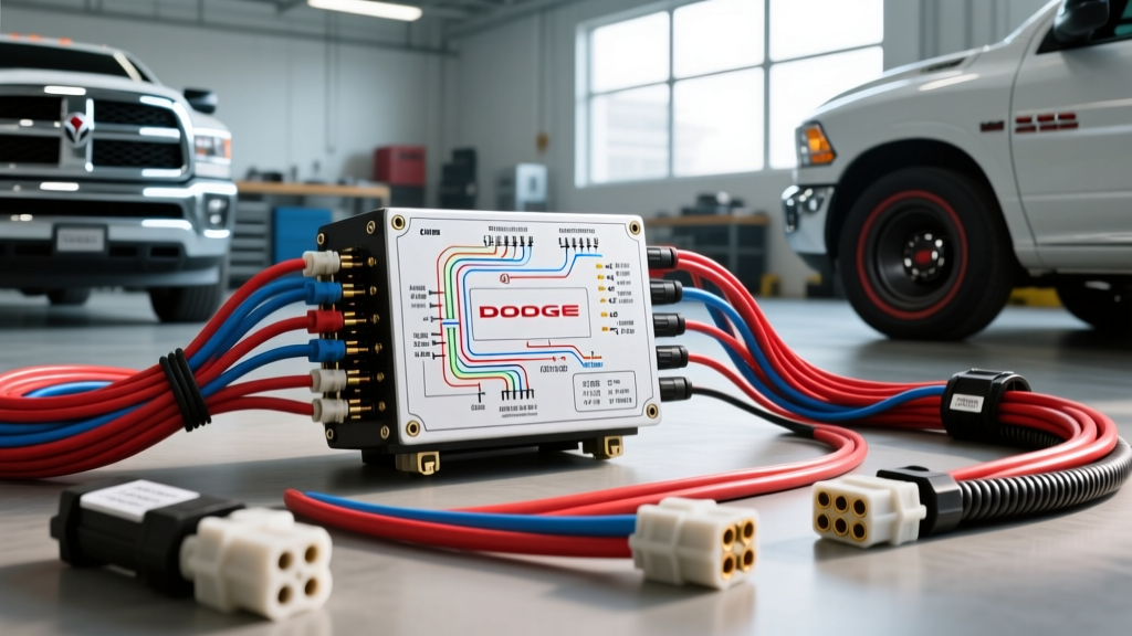
Architectural Overview of Ram Premium Audio Systems
Integrating aftermarket digital signal processors (DSPs) or high-output subwoofers into the Dodge Ram platform requires a fundamental understanding of FCA (Fiat Chrysler Automobiles) electrical architecture. Unlike legacy vehicles that utilized a simple 12V remote turn-on wire and high-level analog speaker outputs, the 3rd and 4th generation Ram trucks (2009-2018) equipped with premium Alpine or Infinity audio systems rely on a Controller Area Network (CAN-bus) and low-level differential audio signaling.
When analyzing the Dodge Ram factory subwoofer wiring diagram, technicians must recognize that the factory amplifier—typically mounted under the rear seat or behind the rear cab wall—acts as the central node for audio distribution, Active Noise Cancellation (ANC), and chime routing. Attempting to tap the subwoofer output wires without accounting for impedance monitoring and CAN-bus wake states will inevitably trigger amplifier protect modes or result in severe signal distortion.
OEM Amplifier Connector Pinout Matrix
The primary interface for the premium audio amplifier is a 22-pin TE Connectivity automotive connector. Below is the definitive pinout matrix for the C3 amplifier connector, detailing wire colors, circuit functions, and American Wire Gauge (AWG) specifications based on Chrysler TechAuthority Wiring Schematics.
| Pin | Wire Color | Circuit Function | AWG |
|---|---|---|---|
| 1 | Red/White Stripe | Fused B+ (Battery Direct) | 10 AWG |
| 2 | Black | Chassis Ground (Z1) | 10 AWG |
| 3 | Dark Green/White | CAN I/O High (D-Bus) | 20 AWG |
| 4 | Dark Green/Brown | CAN I/O Low (D-Bus) | 20 AWG |
| 11 | Dark Green/Orange | Subwoofer Audio (+) | 18 AWG |
| 12 | Dark Green/Yellow | Subwoofer Audio (-) | 18 AWG |
| 15 | White/Red Stripe | ANC Microphone Shield | 22 AWG |
| 16 | White/Black Stripe | ANC Microphone Signal | 22 AWG |
Note: Pinouts may vary slightly between the 8.4-inch Uconnect and 12.1-inch Alpine configurations. Always verify with a digital multimeter (DMM) before cutting or splicing.
Subwoofer Output Terminals and Impedance Matching
The factory subwoofer in the Ram premium systems is typically a Dual Voice Coil (DVC) configuration. The amplifier outputs a bridged signal across Pins 11 and 12. The factory amplifier is calibrated to expect a specific nominal impedance, usually 2 ohms or 4 ohms depending on the exact Alpine/Infinity sub-model installed in the cab enclosure.
The Impedance Monitoring Trap
FCA amplifiers feature active load monitoring. If you disconnect the factory subwoofer to wire in an aftermarket Line Output Converter (LOC) or a high-power aftermarket subwoofer, the amplifier will detect an open circuit (infinite impedance) on Pins 11 and 12. Within 400 milliseconds, the amplifier's internal logic will shut down the subwoofer channel entirely to prevent output stage damage. To bypass this, advanced integrators must use a DSP with an integrated load-matching resistor network (typically a 10-ohm, 5-watt ceramic resistor wired in parallel at the LOC input) to trick the OEM amp into maintaining channel output.
CAN-Bus Wake Signal and Power Management
One of the most common errors when referencing a Dodge Ram factory subwoofer wiring diagram is searching for a 12V remote turn-on lead. It does not exist. The amplifier is powered up via the CAN-bus network.
- CAN High (Pin 3): Resting state is 2.5V. Active state fluctuates between 2.5V and 3.5V.
- CAN Low (Pin 4): Resting state is 2.5V. Active state fluctuates between 1.5V and 2.5V.
When the Uconnect head unit boots, it broadcasts a wake message on the D-Bus. The amplifier's microcontroller reads this differential voltage and closes the internal relay to connect the 10 AWG Fused B+ (Pin 1) to the internal switching power supply. If you are adding an aftermarket amplifier, you must use a CAN-bus interface module (such as a PAC AFD-03 or Maestro AR) to decode the CAN data and generate a clean, 12V / 2A remote turn-on signal for your aftermarket gear. Tapping into the ignition switch or a fuse panel for a remote trigger will result in the aftermarket amp turning on before the OEM amp has booted, causing severe turn-on transients and potential voice coil damage.
Active Noise Cancellation (ANC) Interference
Late-model Rams (2014+) equipped with the premium audio system utilize Active Noise Cancellation to reduce engine drone and road noise. The ANC module injects an inverted phase signal directly into the subwoofer output channel. If you tap the factory subwoofer wires for an aftermarket DSP without disabling the ANC, the aftermarket system will amplify the cancellation frequencies, resulting in a massive, distorted low-frequency rumble that increases with engine RPM.
Technical Fix: You must either physically disconnect the ANC microphone (Pins 15 and 16) and code out the ANC module via an OBDII diagnostic tool (like AlfaOBD or Appcar DiagFCA), or tap the audio signals at the head unit before they reach the ANC processing node.
Diagnostic Decision Tree: Subwoofer Failure Modes
Use the following structured diagnostic tree to isolate faults in the OEM subwoofer circuit, adhering to SAE J1193 Automotive Electrical Standards for testing protocols.
- Symptom: No Bass Output, Amp Draws 0.5A (Sleep Mode)
- Cause: CAN-bus wake signal missing or head unit failure.
- Fix: Probe Pins 3 and 4 with an oscilloscope. If flatline at 2.5V, check Uconnect D-Bus termination resistors (should measure 60 ohms across the bus).
- Symptom: Subwoofer Cuts Out at High Volume (Thermal/Protect)
- Cause: High resistance on the ground circuit or voice coil degradation.
- Fix: Perform a voltage drop test on Pin 2 (Black, 10 AWG). A drop greater than 0.2V at max load indicates a corroded chassis ground. Clean the M6 ground stud and torque to 10 Nm (88 in-lbs).
- Symptom: Engine RPM 'Whine' or Drone in Subwoofer
- Cause: ANC feedback loop or ground loop via RCA shields.
- Fix: Disconnect the ANC mic. If using aftermarket LOCs, ensure RCA shields are grounded at the head unit side only, not at the aftermarket amplifier.
Wire Routing and Environmental Constraints
When extending or replacing the 18 AWG subwoofer output wires, adhere to Mopar Electrical Systems Documentation guidelines. The under-seat amplifier location in the Ram crew cab is highly susceptible to moisture ingress from rear door seals and HVAC condensation. All splices must be sealed using dual-wall heat shrink tubing with marine-grade adhesive. Standard electrical tape or crimp connectors will suffer from galvanic corrosion within 12 months due to the high humidity and temperature cycling under the rear bench.
Summary for Advanced Integrators
Successfully upgrading the Dodge Ram audio system requires moving beyond basic wiring diagrams. By respecting the CAN-bus architecture, managing the DVC impedance expectations, and neutralizing the ANC system, integrators can achieve pristine, high-fidelity bass response without triggering FCA's aggressive OEM protection algorithms. Always verify pinouts with a DMM and consult vehicle-specific technical service bulletins (TSBs) before modifying the factory harness.