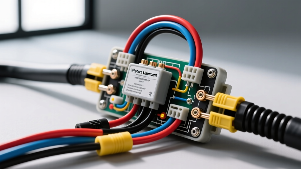
Introduction to the Western Unimount Electrical System
The Western Unimount snow plow system relies on a robust, relay-driven electrical architecture to manage heavy hydraulic loads and exterior lighting. While newer Fleet Flex systems utilize multiplex CAN-bus communication, the classic Western Unimount wiring diagram remains the industry standard for traditional relay-based setups. Understanding this wiring diagram for a Western Unimount plow is critical for upfitters, fleet mechanics, and owner-operators who need to troubleshoot voltage drops, lighting failures, or unresponsive hydraulic valves. This complete walkthrough dissects the power circuits, lighting harness pinouts, and control module configurations required to keep your Unimount system operating flawlessly in extreme winter conditions.
Main Power and Ground Circuit Specifications
The hydraulic power unit (HPU) on a Western Unimount draws massive inrush currents—often exceeding 150 amps during the initial lift phase. Standard automotive wire is entirely insufficient and poses a severe fire hazard. The main power circuit must be built to exact heavy-duty specifications.
Battery to Solenoid Feed
- Wire Gauge: 2 AWG (Minimum). For cable runs exceeding 15 feet from the battery to the solenoid, step up to 1/0 AWG to mitigate voltage drop.
- Wire Type: Must comply with SAE J1128 Low Tension Primary Cable standards for under-hood, high-temperature environments. Use fine-strand, pure copper welding cable for flexibility in freezing temperatures.
- Overcurrent Protection: Install a 250-amp MIDI or ANL fuse within 18 inches of the battery positive terminal.
- Solenoid: Use a continuous-duty, 12V DC solenoid rated for at least 250A (e.g., White-Rodgers 586 series or Trombetta equivalent). Mount the solenoid to a clean, unpainted chassis ground, torquing the mounting hardware to 15 ft-lbs to ensure the solenoid casing acts as a secondary ground path.
Motor Ground Circuit
Do not rely on the plow frame or hitch mounts for the main motor ground. The pivot points and mounting shoes introduce high resistance, especially when corroded by road salt. Run a dedicated 2 AWG ground cable directly from the HPU motor ground stud to the vehicle's engine block or the negative battery terminal. Coat all ring terminals with a high-quality dielectric compound to prevent galvanic corrosion.
Lighting Harness Pinout and Wire Color Codes
The Western Unimount lighting system transfers the vehicle's headlight, turn signal, and marker light circuits to the plow via a molded weather-pack connector. Depending on the exact year and adapter, you will encounter either an 11-pin round or a 9-pin square connector. Below is the standard Western lighting harness wiring diagram mapping.
| Pin | Function | Western Wire Color | AWG Size | Vehicle Side Connection |
|---|---|---|---|---|
| 1 | Chassis Ground | Black | 12 AWG | Engine Block / Chassis |
| 2 | Park / Marker Lights | Brown | 16 AWG | Vehicle Brown Running Light |
| 3 | Left Turn / Stop | Yellow | 16 AWG | Vehicle Left Turn Signal |
| 4 | Right Turn / Stop | Green | 16 AWG | Vehicle Right Turn Signal |
| 5 | Left Headlight (Low Beam) | White | 14 AWG | Vehicle Left Low Beam Feed |
| 6 | Right Headlight (Low Beam) | Blue | 14 AWG | Vehicle Right Low Beam Feed |
| 7 | Left Headlight (High Beam) | Red | 14 AWG | Vehicle Left High Beam Feed |
| 8 | Right Headlight (High Beam) | Orange | 14 AWG | Vehicle Right High Beam Feed |
Note: Always verify pinouts with the specific Western Plows Technical Manuals for your exact harness part number, as HB13 (dual-filament) and H11 (single-filament) headlight adapters utilize slightly different internal relay logic.
Control Harness and Relay Module Walkthrough
The classic Unimount control harness connects the in-cab joystick or handheld pendant to the vehicle-side relay pack. The relay pack acts as the brain, isolating the low-amperage switch circuits from the high-amperage hydraulic valve coils.
Relay Pack Pin Configuration
The vehicle-side control harness typically features a multi-pin connector feeding the relay module. The critical circuits include:
- Red Wire (12V Switched): Connects to a 15A fused ignition-switched power source. This wakes up the relay module when the key is in the 'Run' position.
- Black Wire (Ground): Dedicated 12 AWG ground to the vehicle chassis.
- Blue Wire (Raise/Lift): Trigger wire from the joystick. When energized, it closes the internal relay, sending 12V to the plow's lift valve coil and the main power solenoid.
- White Wire (Lower): Trigger wire for the lower valve coil.
- Green / Yellow Wires (Left/Right Angles): Trigger wires for the angle valve coils.
Hydraulic Valve Coil Specifications
The solenoid valves on the Unimount HPU are typically 12V DC, drawing between 2.5 and 4 amps each. When troubleshooting a non-functioning hydraulic function, disconnect the coil and measure the resistance across the two spade terminals using a digital multimeter. A healthy Western Unimount valve coil should read between 10 and 16 ohms. A reading of infinite resistance (OL) indicates a burnt internal winding, while a reading near 0 ohms indicates a shorted coil that will blow your in-cab control fuse.
Step-by-Step Firewall Routing and Weatherproofing
Improper routing is the leading cause of Unimount control harness failures. The engine bay is a hostile environment characterized by extreme heat, vibrating components, and corrosive magnesium chloride road treatments.
- Identify the Firewall Pass-Through: Utilize an existing factory grommet if your truck is equipped with a 'Snow Plow Prep' package. If drilling a new hole, use a step-bit to create a clean edge and immediately install a rubber firewall grommet to prevent the metal from shearing the wire insulation.
- Loom and Lacing: Encase the control and lighting harnesses in split-loom tubing. Secure the loom every 8 inches using UV-resistant zip ties or automotive cloth tape (Tesa harness tape). Never use standard vinyl electrical tape under the hood; the adhesive melts and unravels within one summer season.
- Connector Weatherproofing: Before mating the plow-side and vehicle-side connectors, apply a generous amount of dielectric grease to the pins. This displaces moisture and prevents the formation of copper oxide, which causes high-resistance voltage drops. Refer to Ford Motor Company Upfitter Guidelines for approved chemical compounds that will not degrade the rubber weather seals.
Common Failure Modes and Multimeter Diagnostics
When the plow fails to operate, mechanics often immediately suspect the hydraulic pump. However, 80% of Unimount failures are electrical. Use this diagnostic decision tree to isolate the fault.
Symptom: Clicking Solenoid but No Motor Movement
Cause: High resistance in the main power or ground circuit, or worn solenoid contacts. Fix: Perform a voltage drop test. Set your multimeter to DC Volts. Place the red probe on the battery positive terminal and the black probe on the motor-side stud of the solenoid. Have an assistant press the 'Raise' button on the joystick. A voltage drop reading greater than 0.5V under load indicates a corroded cable, a loose terminal, or failing internal contacts within the solenoid. Replace the 2 AWG cable or the solenoid accordingly.
Symptom: Plow Headlights Flicker or Dim on High Beam
Cause: Inadequate ground path at the plow frame or a failing lighting isolation relay. Fix: Check the Pin 1 (Black) ground wire. Measure resistance from the plow-side connector ground pin to the bare metal of the plow moldboard. It should read less than 0.5 ohms. If the ground is solid, test the output voltage at the relay pack's high-beam feed wires (Red and Orange). If voltage drops below 11.5V when the plow lights are engaged, the internal relays in the lighting module are pitted and the module must be replaced.
Symptom: Joystick Lights Do Not Illuminate
Cause: Loss of switched 12V power or blown inline fuse. Fix: Locate the inline fuse holder on the Red (switched power) wire near the relay pack. Verify continuity across the fuse. If the fuse is intact, probe the Red wire at the relay pack connector with the ignition ON. You should read battery voltage (12.4V - 12.8V). If 0V is present, trace the Red wire back to the ignition fuse panel to locate a broken splice or blown upfitter fuse.