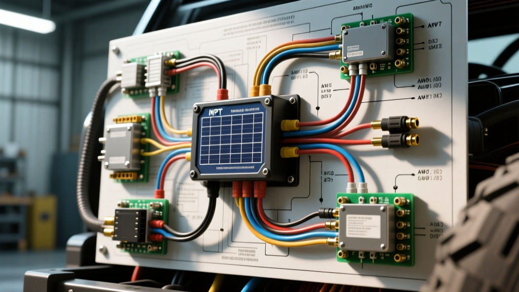
Vehicle Solar Charge Controller Wiring Diagram & Integration Guide
Integrating a Maximum Power Point Tracking (MPPT) solar charge controller into an expedition vehicle, camper van, or overland truck requires strict adherence to mobile DC electrical standards. Unlike stationary residential setups, automotive environments subject wiring to severe vibration, thermal cycling, and corrosive elements. This technical specification reference provides a comprehensive wiring diagram solar charge controller layout tailored for 12V and 24V mobile dual-battery systems.
A poorly executed solar installation can lead to catastrophic voltage drop, inefficient battery charging, or DC arc flash fires. By following the pinouts, AWG sizing charts, and torque specifications detailed below, you will ensure your vehicle's house battery bank receives optimal, safe, and regulated solar current.
Core System Architecture: MPPT to House Battery
The standard overland solar architecture routes DC power from the roof-mounted photovoltaic (PV) array through a weatherproof cable gland into the vehicle cabin. The PV input connects directly to the MPPT controller's solar terminals. The controller's battery output terminals are then wired to a DC distribution busbar, which is tied to the lithium iron phosphate (LiFePO4) or AGM house battery bank.
Crucially, the MPPT controller must never be connected to the vehicle's starting battery without an ignition-sense isolation relay, as the controller's quiescent draw (typically 10mA to 25mA) will parasitically drain the cranking battery over extended parking periods. Furthermore, the battery terminals on the charge controller must always be connected before the PV array terminals. Connecting the solar array first can cause voltage spikes that destroy the controller's internal microprocessor, as the controller requires the battery to establish its baseline system voltage (12V/24V auto-detect).
Wire Gauge, Color Code, and Overcurrent Specifications
The following table outlines the minimum American Wire Gauge (AWG) requirements and overcurrent protection devices (OCPD) for a standard 40A MPPT solar charge controller operating on a 12V nominal system. All wiring must be fine-stranded, SAE J1128 or UL 1015 compliant copper to withstand vehicular vibration.
| Circuit Path | Max Current | Wire Gauge (AWG) | Insulation Color | OCPD Type & Rating | |
|---|---|---|---|---|---|
| PV Array to MPPT Input | 30A - 40A | 10 AWG (Stranded) | Yellow (+) / Black (-) | 40A DC Breaker or Fuse | |
| MPPT Output to Busbar/Battery | 40A - 50A | 6 AWG (Fine Strand) | Red (+) / Black (-) | 50A Class T or ANL Fuse |
Note: For runs exceeding 5 feet (1.5 meters) between the MPPT controller and the battery bank, step up the output wire to 4 AWG to maintain a voltage drop below 1.5% during the absorption charging phase.
Terminal Pinout and Physical Connections
Most premium MPPT controllers (such as those from Victron Energy or Morningstar) utilize M5 or M6 screw terminal blocks. Proper termination is critical to prevent high-resistance connections that generate excessive heat.
1. Preparation and Crimping
Never insert bare, frayed stranded wire directly into a screw terminal. The clamping force will shear the outer strands, reducing the effective cross-sectional area and creating a hot spot. You must use DIN 46228 compliant bootlace ferrules. Strip the wire precisely to the ferrule's copper tube length (usually 8mm to 10mm), insert, and crimp using a ratcheting ferrule crimper. The crimp must pass a pull-test of at least 30 lbs.
2. Torque Specifications
Over-torquing terminal screws will strip the brass threaded inserts molded into the controller's plastic housing. Under-torquing leads to arcing. Always use a calibrated torque screwdriver.
- M5 Terminal Screws: Tighten to 1.2 Nm - 1.5 Nm (10.6 - 13.2 in-lbs).
- M6 Terminal Screws: Tighten to 2.0 Nm - 2.5 Nm (17.7 - 22.1 in-lbs).
3. Pin Assignments
- Terminals 1 & 2 (PV Input): Terminal 1 is Positive (+), Terminal 2 is Negative (-). Ensure the PV disconnect breaker is in the OFF position during termination.
- Terminals 3 & 4 (Battery Output): Terminal 3 is Positive (+), Terminal 4 is Negative (-). The inline ANL fuse must be removed or the breaker OPEN while terminating.
- Terminals 5 & 6 (Load Output - if equipped): Used for direct DC loads. Note that the load output is electronically switched and typically limited to 15A-20A. Do not use this for high-draw inverters.
Ignition Sense and BMS Communication Wiring
Advanced vehicle wiring diagrams for solar charge controllers incorporate communication buses and ignition triggers to protect the vehicle's electrical ecosystem.
VE.Direct / RS485 Communication
Modern MPPT controllers feature a communication port (e.g., VE.Direct) used to transmit telemetry data to a Bluetooth dongle or a centralized battery monitor (shunt). Use a 4-pin JST or Molex connector with 22 AWG shielded twisted-pair cable. Route this data cable at least 4 inches away from the main DC power cables to prevent electromagnetic interference (EMI) from corrupting the data stream.
Ignition Cut-Off Relay Integration
If your MPPT controller is wired to the vehicle's starter battery (not recommended, but common in simpler setups), you must wire an ignition-sense relay. Connect a 14 AWG wire from an ignition-switched 12V source (e.g., the cigarette lighter circuit or a fuse tap on the ignition relay) to the controller's 'Engine Running' or 'Relay Control' pin. This signals the controller to cease all charging and enter sleep mode when the alternator is active, preventing voltage conflicts between the alternator's regulator and the MPPT's charging algorithm.
Grounding Standards for Mobile Solar Systems
According to ABYC E-11 standards for mobile DC electrical systems, all negative returns should be consolidated to a central negative DC busbar, rather than relying on the vehicle's steel chassis as a ground return path for high-current solar circuits. The chassis is highly susceptible to rust, paint insulation, and varying resistance, which can cause the MPPT controller to misread the battery voltage.
- Run a dedicated 6 AWG or 4 AWG black negative wire from the MPPT's Terminal 4 directly to the negative busbar.
- From the negative busbar, run a heavy-gauge cable (matching the main positive battery cable, e.g., 2/0 AWG) to the vehicle's main chassis ground point.
- Scrape away all paint, primer, and rust at the chassis ground point down to bare metal.
- Apply a dielectric grease or anti-corrosion compound (e.g., No-Ox-Id) to the ring terminal before bolting it to the chassis with a stainless steel bolt and nylock nut.
Troubleshooting Common MPPT Integration Faults
When the system fails to perform as expected, use this diagnostic matrix to identify the root cause based on the controller's LED indicators or Bluetooth telemetry.
| Symptom | Probable Cause | Corrective Action |
|---|---|---|
| Controller shows 0V PV Input despite bright sunlight. | Tripped PV breaker, blown inline fuse, or reversed PV polarity. | Verify continuity of PV wires. Reset breaker. Check for tripped internal diode protection. |
| Battery fails to reach Absorption voltage (stuck in Bulk). | Excessive voltage drop between MPPT battery terminals and actual battery posts. | Measure voltage directly at battery posts vs. MPPT terminals under load. Upgrade wire gauge or clean busbar connections. |
| MPPT controller overheating and derating current. | Poor terminal crimp causing high resistance, or inadequate ventilation. | Inspect ferrule crimps for splaying. Ensure controller is mounted vertically with 4 inches of clearance for convective cooling. |
| Erratic charging state (bouncing between Bulk and Float). | EMI interference on the battery sense wire or loose ground connection. | Route sense wires away from AC inverter cables. Tighten negative busbar chassis ground to bare metal. |
Voltage Drop Calculations for PV Array Wiring
To maximize the efficiency of your solar harvest, the voltage drop on the PV input side must be minimized. MPPT controllers require the PV array voltage (Vmp) to be significantly higher than the battery voltage to operate. If the wire gauge is too small, resistance will drop the voltage below the MPPT's minimum startup threshold, especially on hot days when panel voltage naturally decreases.
Use the following formula to calculate voltage drop for your roof-to-controller run:
Voltage Drop (V) = (2 x Length x Current x Wire Resistance per 1000ft) / 1000
For a 30A array using 10 AWG wire (Resistance = 1.018 ohms/1000ft) over a 15-foot one-way run:
Vd = (2 x 15 x 30 x 1.018) / 1000 = 0.91 Volts.
If your Vmp is 18V, a 0.91V drop is roughly 5%, which is acceptable but borderline. Upgrading to 8 AWG wire reduces this drop to 0.57V (3.1%), ensuring the MPPT algorithm has maximum voltage headroom to track the power curve accurately. For detailed wire resistance metrics, refer to the SAE J1128 battery cable specifications.
Authoritative References and Further Reading
When designing and executing mobile solar integrations, always consult the latest engineering standards to ensure safety and compliance. The procedures outlined in this wiring diagram solar charge controller guide are derived from the following authoritative resources:
- American Boat & Yacht Council (ABYC) E-11 Standard - AC & DC Electrical Systems on Boats (Widely adopted as the gold standard for mobile/marine DC wiring and overcurrent protection).
- SAE International J1128 - Low Tension Primary Cable specifications for automotive wire insulation and thermal ratings.
- Victron Energy MPPT Controller Manuals - Specific torque values, VE.Direct pinouts, and error code matrices for industry-leading mobile solar controllers.
By strictly adhering to these AWG requirements, crimping standards, and grounding topologies, your vehicle's solar electrical system will deliver reliable, off-grid power for years of overland exploration.