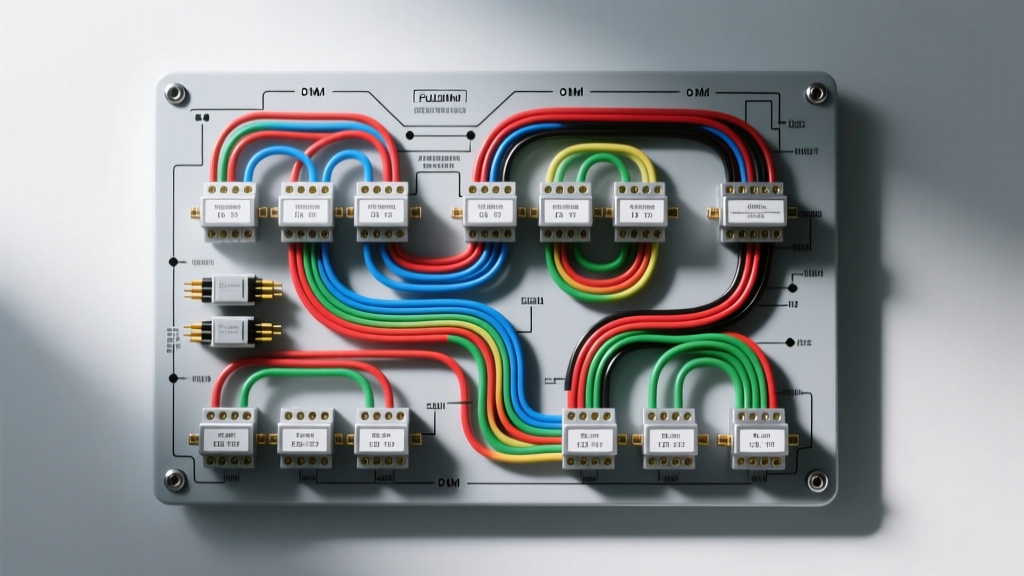
Decoding Modern Remote Starter Wiring Diagrams
Remote starter wiring diagrams have evolved from simple analog relay pack schematics to complex digital integration blueprints. In modern vehicles (2010-present), the ignition switch no longer carries the full amperage required to power the vehicle's ECM, BCM, and fuel pumps. Instead, it sends low-current multiplexed signals over data networks. Therefore, interpreting remote starter wiring diagrams requires a firm grasp of both high-current 12V+ distribution and low-voltage CAN-bus data topologies. This technical specification reference details the universal harness pinouts, AWG requirements, and OEM data integration protocols necessary for flawless, safe, and reliable remote start installations across diverse automotive platforms.
Primary Power and Ground Distribution Specifications
The foundation of any reliable remote start system lies in its power and ground distribution. According to the Mobile Electronics Certification Program (MECP) guidelines, the main 12V+ constant power wire (universally color-coded RED in aftermarket harnesses) must be a minimum of 10 AWG stranded copper. This wire should be routed directly to the vehicle's high-amp fuse block or battery positive terminal, protected by an inline MAXI fuse rated 25% higher than the module's maximum draw (typically a 30A or 40A fuse).
The ground wire (BLACK) must also be 10 AWG, terminated with a copper ring terminal, and secured to a bare, unpainted chassis ground point using a star washer and OEM-grade hardware. The ground wire length must never exceed 18 inches to prevent voltage drop and ground loop interference. Excessive ground wire length is the primary cause of module reboots during the high-current draw of the starter motor engagement, leading to crank-no-start failures.
Standard 24-Pin Main Harness Pinout Reference
While specific manufacturers like Compustar, Viper, and Avital utilize proprietary connectors, the underlying 24-pin primary harness logic remains highly standardized across the industry. Below is the technical pinout specification for the main logic harness.
| Pin | Wire Color | Function | Polarity / Spec |
|---|---|---|---|
| 1 | RED | 12V+ Constant Input | (+) 10 AWG, 30A Fused |
| 2 | BLACK | Chassis Ground | (-) 10 AWG, Ring Terminal |
| 3 | YELLOW | Ignition 1 (Primary) | (+) 14 AWG, 10A Relay |
| 4 | PINK | Ignition 2 (Secondary/ECM) | (+) 14 AWG, 10A Relay |
| 5 | ORANGE | Accessory 1 | (+) 14 AWG, 10A Relay |
| 6 | PURPLE | Starter Output | (+) 12 AWG, 30A Relay |
| 7 | BROWN | Parking Light Output | (+) 18 AWG, 10A Max |
| 8 | WHITE | Parking Light Input | (-) 18 AWG, Data/Diode |
| 9 | GREEN | Tachometer Input | AC Ripple, 1.5V - 5.0V |
| 10 | GRAY | Hood Pin Safety Input | (-) Ground to Abort |
| 11 | BROWN/WHITE | Brake Pedal Input | (+) 12V to Shutdown |
| 12 | BLUE | Door Lock Output | (-) 500mA Pulse |
Heavy-Gauge Relay Satellite Configuration
Remote starter wiring diagrams for the heavy-gauge ignition harness usually feature a 10-pin or 12-pin Molex MX150 connector. This satellite relay pack handles the high-current switching (20A-30A per circuit) for Ignition, Accessory, and Starter outputs. The PURPLE wire (Starter) must be wired to the starter side of the vehicle's neutral safety switch or clutch interlock relay. Failing to wire through the safety interlock creates a severe hazard where the vehicle could remote start while in gear. The heavy gauge wires must be 12 AWG minimum, and the relay pack must be mounted in a well-ventilated area, as the internal 30A Bosch-style relays generate significant heat during the 1.5 to 3-second crank cycle.
OEM CAN-Bus and Immobilizer Integration
Analog remote starter wiring diagrams are obsolete for modern push-to-start vehicles. Bypassing factory immobilizers (like Ford PATS, GM Passlock, or Chrysler SKIM) requires a digital interface module such as the Fortin EVO-ALL or the iDatalink Maestro RR. These modules intercept the vehicle's CAN-bus network. When referencing OEM wiring schematics, technicians must locate the CAN-High (CAN-H) and CAN-Low (CAN-L) twisted pair.
For example, on a standard GM Global A/B architecture, CAN-H is typically Dark Green and CAN-L is Dark Blue at the OBD2 port pins 6 and 14. The remote starter's data bus output (often a 4-pin or 5-pin proprietary connector utilizing the D2D or W2W protocol) connects directly to the interface module. This digital handshake eliminates the need to manually wire tach signals, door locks, and brake inputs, relying instead on multiplexed data packets broadcast by the BCM.
Safety Inputs and Tachometer Calibration
Safety circuits are non-negotiable in remote starter wiring diagrams. The Hood Pin input (GRAY or BLACK/WHITE) is a critical safety shutdown circuit. It must be wired to a mechanical plunger switch or integrated via CAN-bus. If the hood pin circuit reads open (ground fault) during a remote start attempt, the module will abort the sequence and flash the parking lights three times.
When utilizing an analog tach wire (typically GREEN), the module must be programmed to learn the vehicle's AC tach ripple voltage from the fuel injector control wire or ignition coil negative terminal. If the learned voltage is too low (below 1.5V AC), the module will crank the starter but cut it prematurely, or fail to recognize the engine has started, resulting in a starter grind.
Wiring Connection Standards and Best Practices
Splicing methodology is critical to long-term reliability. T-taps and scotch locks are strictly prohibited in professional remote starter wiring diagrams due to their tendency to cause micro-fractures in OEM wiring and induce galvanic corrosion. SAE J1128 standards for low-tension primary cable dictate that splices must maintain the original wire's current-carrying capacity and flexibility. The industry standard is the modified Western Union splice, soldered with rosin-core flux, and sealed with dual-wall polyolefin heat shrink tubing containing an inner adhesive layer. This ensures a moisture-proof, vibration-resistant connection that meets OEM durability specifications.
Troubleshooting: Crank-No-Start and Data Failures
When diagnosing a crank-no-start condition via remote start, technicians must follow a structured decision tree:
- Analog Systems: Verify the tach signal. Use a digital multimeter set to AC Voltage to probe the tach input wire during manual cranking. If the voltage is erratic or below 1.5V, relocate the tach source to the alternator post or a different fuel injector.
- Immobilizer Bypass: If the vehicle cranks but immediately dies, the immobilizer bypass module has failed to broadcast the transponder unlock sequence. Verify the bypass module's programming LED. A solid red light during crank indicates a firmware mismatch or a dropped CAN-bus connection.
- CAN-Bus Voltage Check: Use an oscilloscope to verify CAN-bus differential voltage. CAN-H should idle around 2.5V and rise to 3.5V during transmission; CAN-L should idle around 2.5V and drop to 1.5V. If both lines sit at 12V or 0V, the data bus is shorted or the interface module has failed.
- Brake Switch Fault: A faulty stoplight switch can send a phantom 12V+ signal to the BROWN/WHITE brake input wire, causing the module to instantly shut down the engine upon starting. Disconnect the brake input wire at the module to isolate this variable.
By adhering strictly to these technical specifications and referencing accurate remote starter wiring diagrams, installers can eliminate parasitic draws, prevent ECM damage, and ensure seamless OEM-level integration.