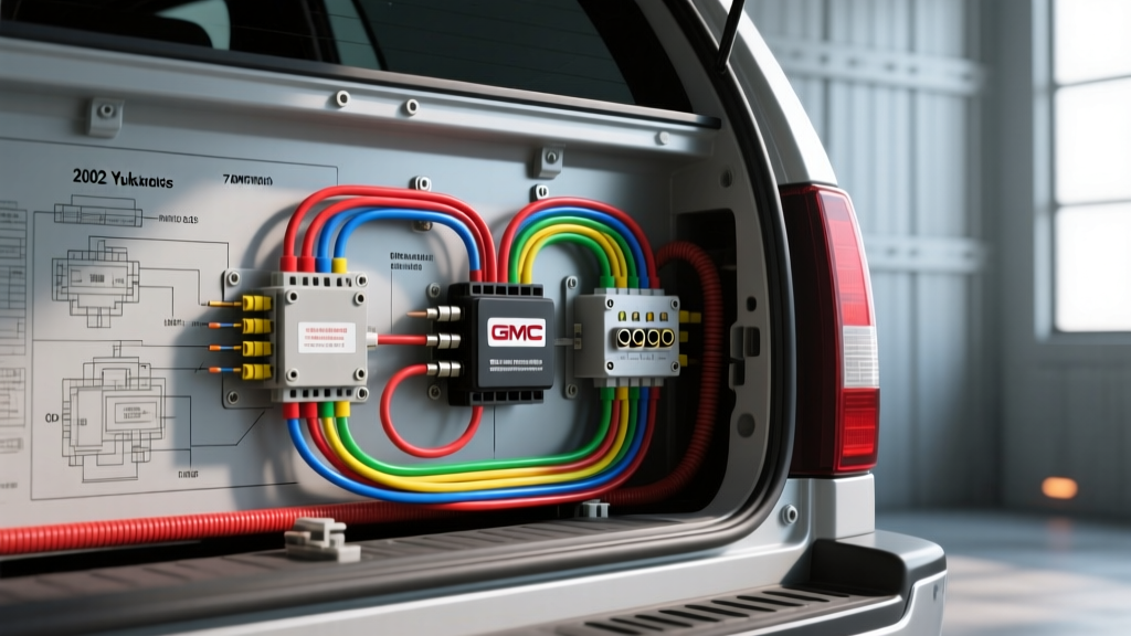
Introduction to the GMT800 Electrical Architecture
When consulting a 2002 GMC Yukon wiring diagram for heavy-duty towing upgrades, it is critical to understand the underlying GMT800 platform electrical architecture. Unlike older vehicles that routed trailer lighting directly from the headlight or turn signal switches, the 2002 Yukon utilizes a sophisticated Body Control Module (BCM) and a Rear Junction Block (RJB) to manage trailer lighting circuits. This isolated circuit design protects the vehicle's primary lighting and BCM from trailer-side shorts and voltage drops.
Whether you are replacing a damaged OEM 7-way RV blade connector, adding a factory-style tow package to a base-model Yukon, or wiring a proportional brake controller, this practical installation guide provides the exact OEM wire colors, AWG specifications, and pinout configurations required for a safe, reliable setup.
Pre-Installation: Verifying RPO Codes and Fuses
Before cutting any wire or ordering a replacement harness, check your Yukon's Service Parts Identification (SPID) sticker located inside the glovebox. You are looking for RPO Z82 (Trailering Provisions). If your vehicle has Z82, the factory blunt-cut wires for the brake controller and the rear 7-way connector are already present and bundled in foam tape. If your Yukon lacks Z82, you will need to run dedicated circuits from the Underhood Electrical Center (UEC) to the rear of the vehicle.
Required Tools and Materials
- Wire Strippers & Crimpers: Capable of handling 10 AWG to 16 AWG wire.
- Heat Shrink Tubing: Adhesive-lined, 3:1 shrink ratio for waterproofing exterior connections.
- Digital Multimeter (DMM): For verifying BCM outputs and ground continuity.
- OEM Replacement Harness: Hopkins 40975 or AC Delco PT1357 (7-way to RJB pigtail).
- Self-Tapping Ground Screws: #10 or #12 with star washers for bare metal frame grounding.
Understanding the Rear Junction Block (RJB) & 7-Way Pinout
The Rear Junction Block is located behind the rear bumper on the driver's side frame rail. It serves as the central distribution point for all trailer lighting. The OEM harness plugs directly into the RJB, drawing power from dedicated fuses in the Underhood Electrical Center (UEC). According to SAE J286 Trailer Connector Standards and GM Upfitter guidelines, the 7-way RV blade must adhere to strict color-coding and gauge requirements to prevent voltage drop over the length of the vehicle.
| 7-Way Pin Position | Function | OEM Wire Color | Minimum AWG |
|---|---|---|---|
| Pin 1 (Top Left) | Left Turn / Stop | Yellow | 16 AWG |
| Pin 2 (Bottom Left) | Reverse / Aux | Light Blue | 16 AWG |
| Pin 3 (Bottom Center) | Ground | White | 10 AWG |
| Pin 4 (Top Right) | Right Turn / Stop | Dark Green | 16 AWG |
| Pin 5 (Top Center) | 12V Battery Feed | Red | 10 AWG |
| Pin 6 (Bottom Right) | Tail / Running Lights | Brown | 16 AWG |
| Pin 7 (Center) | Electric Brake Output | Dark Blue | 12 AWG |
Step-by-Step 7-Way Trailer Harness Installation
Step 1: Access the Underhood Electrical Center (UEC)
Open the hood and locate the UEC on the driver's side. Verify the presence of the trailering relays and fuses. You must ensure the TRAILER BCK/UP (30A) and TRRLR (15A) fuses are seated properly. If your Yukon did not come with the Z82 package, you will need to install these fuses and the corresponding OEM relays to activate the RJB circuits.
Step 2: Route the Harness to the Rear Junction Block
Carefully lower the spare tire to gain access to the rear crossmember. Locate the RJB connector plugged into the driver-side frame rail. Unclip the locking tab and disconnect the old harness. Inspect the male pins on the vehicle-side RJB connector for green corrosion (copper oxide). If present, clean with electrical contact cleaner and a brass brush.
Step 3: Establish a True Chassis Ground
The most common failure point in GMT800 trailer wiring is a poor ground. The 10 AWG White wire from the 7-way plug must be grounded directly to the steel frame. Do not rely solely on the RJB ground path. Use a self-tapping screw with a star washer to bite through the factory E-coat and bare metal on the frame rail near the hitch receiver. Apply dielectric grease over the screw head to prevent rust.
Step 4: Connect and Secure the 7-Way Plug
Plug the new harness into the RJB until the locking tab clicks. Route the wiring loom along the factory harness clips, ensuring the Dark Blue (brake) and Red (12V aux) wires are kept away from the exhaust muffler, which can melt the insulation and cause a dead short to the chassis.
Proportional Brake Controller Wiring (Under-Dash Port)
For towing trailers with electric brakes, a proportional brake controller is mandatory. The GM Upfitter Body Builder Manuals dictate that GMT800 trucks with the Z82 package feature a pre-wired blunt-cut harness tucked under the dash, eliminating the need to splice into the stoplamp switch pedal assembly.
Locate the wiring bundle tucked above the emergency brake pedal or behind the left kick panel data link connector (DLC) area. It is typically wrapped in a foam sleeve and taped shut. You will find four distinct wires intended for the brake controller pigtail.
| GM OEM Wire Color | Function | Brake Controller Pigtail Wire |
|---|---|---|
| Red | 12V Battery Feed (Fused) | Black (or Red depending on brand) |
| Dark Blue | Output to Trailer Brakes | Blue |
| Light Blue | Stoplamp Switch Signal | Red |
| White | Chassis Ground | White |
Note: Always verify the Light Blue wire with a multimeter. It should read 0V at rest and 12V when the brake pedal is depressed. If it reads 12V at rest, you have identified the wrong circuit.
Troubleshooting Common GMT800 Electrical Gremlins
1. Trailer Running Lights Not Illuminating (Brown Wire)
Cause: The BCM isolates the trailer running lights via the TRRLR 15A fuse in the UEC. If this fuse is blown, or if the BCM detects a short on the Brown wire, it will shut down the circuit to protect the vehicle.
Fix: Check the TRRLR fuse. If intact, use a DMM to test the Brown wire at the RJB for 12V with the headlights on. If no voltage is present, inspect the trailer plug for crushed pins or frayed insulation near the hitch.
2. Hyperflashing with LED Trailer Upgrades
Cause: The 2002 Yukon uses a solid-state flasher module (typically LM446) located in the convenience center on the left side of the dash. LED trailer lights draw significantly less amperage than incandescent bulbs, causing the BCM to interpret the low draw as a blown bulb, resulting in rapid hyperflashing.
Fix: Replace the OEM LM446 flasher relay with an LED-compatible LM449 or heavy-duty electronic flasher. This bypasses the bulb-out warning logic while maintaining proper flash cadence.
3. Brake Controller Displays 'SH' (Short Circuit)
Cause: The Dark Blue brake output wire is shorting to the chassis ground before reaching the 7-way plug.
Fix: Disconnect the Dark Blue wire at the under-dash harness and at the rear RJB. Use a multimeter in continuity mode to test the Dark Blue wire against the bare chassis. If continuity exists, the wire is pinched—commonly where the harness passes through the rear bumper bracket or where it rubs against the spare tire winch mechanism. Reroute and wrap in split-loom tubing.