Introduction to the Vanguard V-Twin Engine Swap
Custom vehicle builders, off-road buggy fabricators, and heavy-equipment restorers frequently rely on Briggs & Stratton Vanguard or Intek V-twin engines for their reliability and high torque output. When executing an engine swap into a custom chassis, integrating the engine's electrical system into a custom dashboard is a critical hurdle. Unlike modern automotive ECUs that require complex CAN-bus handshakes, small engine ignitions are relatively straightforward, yet they possess unique quirks that can destroy components if wired incorrectly. This guide provides a comprehensive breakdown of the schematic Briggs and Stratton ignition coil wiring diagram, focusing on upgrade projects that involve custom key switches, safety kill relays, and aftermarket tachometer integration.
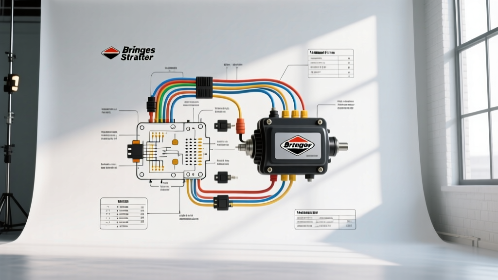
Decoding the Schematic Briggs and Stratton Ignition Coil Wiring Diagram
To properly wire a B&S engine into a custom vehicle, you must first understand that the OEM ignition schematic is fundamentally a kill circuit, not a power circuit. The vast majority of Briggs & Stratton V-twins utilize the patented Magnetron solid-state ignition system. This system generates its own high-voltage spark independently of the vehicle's 12V battery. The only electrical wire connected directly to the ignition coil is the primary kill wire, which functions by grounding the coil's primary winding to collapse the magnetic field and prevent spark generation.
The Magnetron Principle vs. Traditional 12V Systems
In a traditional automotive 12V ignition system, the coil requires a switched 12V+ feed to charge the primary winding. In the Magnetron system, a permanent magnet embedded in the engine flywheel passes over the coil's laminated iron core, inducing the necessary voltage. Therefore, routing a 12V+ wire from your custom dash directly to the B&S ignition coil terminal will instantly fry the internal diode and resistor network, permanently destroying the coil. The schematic strictly dictates that the coil wire must only ever route to a ground path via the ignition switch.
Wire Color Codes, AWG Sizing, and Pinout Specifications
When extending the OEM harness to a custom dash in a buggy or tractor build, adhering to proper AWG sizing and color codes prevents voltage drop and diagnostic confusion. Below is the specification chart for extending the Vanguard V-twin ignition and solenoid circuits.
| Circuit Function | OEM Wire Color | Recommended AWG | Terminal / Connector Type | Destination / Pinout |
|---|---|---|---|---|
| Ignition Kill (Primary Ground) | Black/Yellow Stripe | 16 AWG Stranded TXL | 1/4' Insulated Spade | Key Switch 'M' (Magneto) |
| Anti-Afterfire Solenoid (12V+) | Red (Fusible Link) | 14 AWG Stranded TXL | 1/4' Ring Terminal | Key Switch 'A' (Accessory) |
| Main Engine Ground | N/A (Bare/Braided) | 10 AWG Braided Strap | 5/16' Ring Terminal | Chassis Ground Bus Bar |
| Starter Solenoid Trigger | White/Red Stripe | 12 AWG Stranded TXL | 1/4' Spade | Key Switch 'S' (Start) |
Upgrade Project: Integrating a Custom Dash and Key Switch
For this upgrade project, we are adapting a 27HP Briggs & Stratton Vanguard V-twin to a custom Cole Hersee 5-position ignition switch mounted in a fabricated steel dash. This setup will control the ignition kill, the starter solenoid, the carburetor fuel solenoid, and an accessory bus.
Step 1: Routing the Kill Wire to the Ignition Switch
Locate the black wire with a yellow stripe exiting the engine blower housing. This is your primary kill wire. Extend this wire using 16 AWG TXL (Cross-Linked Polyethylene) automotive wire. TXL wire is essential for off-road and tractor builds due to its high heat resistance and thin insulation profile, which allows for tighter harness routing. Use adhesive-lined, dual-wall heat shrink (3:1 shrink ratio) over all crimp connections to prevent moisture ingress, which is a leading cause of phantom grounding and 'no-spark' conditions in outdoor vehicles. Connect the extended kill wire to the 'M' (Magneto) terminal on the ignition switch. When the key is turned to OFF, the 'M' terminal internally bridges to the switch casing (Ground), killing the spark.
Step 2: Wiring the Anti-Afterfire Fuel Solenoid
Vanguard engines feature a 12V anti-afterfire solenoid on the base of the carburetor bowl. This solenoid requires 12V+ whenever the key is in the ON or START position to retract the plunger and allow fuel into the main jet. Wire a 14 AWG red lead from the solenoid to the 'A' (Accessory) or 'B' (Battery) terminal on the key switch. If your dash includes multiple high-draw accessories, use a standard 30A Bosch-style automotive relay to handle the solenoid load, triggering the relay coil with the key switch to prevent melting the dash switch contacts.
Step 3: Tachometer Signal Extraction
Because the Magnetron coil lacks a traditional negative terminal for a hardwired tachometer signal, custom builders must use an inductive pickup clamp. Wrap the inductive sensor around the #1 cylinder spark plug wire. Route the 3-pin sensor harness: Pin 1 to a switched 12V+ source, Pin 2 to a clean chassis ground, and Pin 3 to the signal input on a diesel/racing tachometer calibrated for small-engine pulse rates (typically 1 pulse per revolution for single-cylinder, or specific V-twin calibration settings).
Real-World Troubleshooting and Failure Modes
Even with a perfect schematic execution, custom swaps introduce new variables that can mimic ignition failure. Use this decision tree to diagnose issues.
Symptom-Cause-Fix Decision Tree
- Symptom: Engine runs but will not shut off when the key is turned to OFF.
Cause: Broken kill wire or isolated engine block (ground loop). The engine is not grounded to the chassis, so the kill wire cannot complete the ground circuit.
Fix: Install a 10 AWG braided copper ground strap between the engine block mounting bolt and the vehicle chassis. Ensure the key switch casing is properly grounded. - Symptom: Weak, intermittent yellow spark; engine backfires through the carburetor.
Cause: Sheared flywheel key. The flywheel has slipped on the crankshaft taper, altering the ignition timing by several degrees.
Fix: Remove the flywheel using a dedicated puller (never pry or hammer). Inspect the Woodruff key. Replace the key and torque the flywheel nut to 100 ft-lbs using a strap wrench and thread locker. - Symptom: No spark on one or both cylinders.
Cause: Improper Magnetron air gap or physical strike damage.
Fix: Measure the gap between the coil's laminated core and the flywheel magnet using a brass feeler gauge. Adjust to exactly 0.010' - 0.012' (0.25 - 0.30 mm). Torque the coil mounting bolts to 35 in-lbs. Avoid using steel feeler gauges, as the magnetic pull will skew the measurement.
Authoritative References
For further technical validation and OEM torque specifications, consult the following resources:
- Briggs & Stratton Vanguard V-Twin Service Manuals - Official OEM wiring schematics, air gap specifications, and magnetron testing procedures.
- SAE J1128: Low Tension Ignition Cable Standard - Society of Automotive Engineers standards for wire insulation, voltage drop, and temperature ratings in small engine applications.
- Cole Hersee Ignition Switch Technical Reference - Comprehensive pinout matrices for 'M', 'G', 'B', 'A', and 'S' terminals in custom automotive and off-road dash integrations.