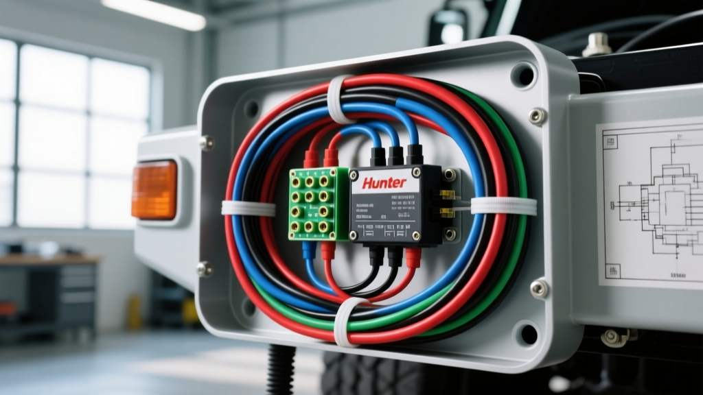
Mobile Skid Unit Upfit: Integrating Landscape Controls into Heavy-Duty Trucks
Landscaping contractors, agricultural operations, and municipal fleets frequently mount custom water tanks, high-pressure pumps, and solenoid valve manifolds onto heavy-duty truck beds. These mobile skid units are essential for dust control, estate management, and remote irrigation. To automate zone valve control directly from the vehicle, upfitters often integrate a commercial-grade Hunter irrigation controller (such as the X-Core or Pro-C) into the truck's electrical system. However, bridging the gap between a 12VDC automotive chassis and a 24VAC landscape controller requires precise electrical engineering to prevent catastrophic component failure.
This comprehensive upfit guide details the exact wiring diagram, Hunter irrigation controller integration steps, and automotive-grade harness specifications required to safely power landscape solenoids from a Ford F-Series or Chevy Silverado HD chassis. By adhering to SAE J1128 standards for low-tension primary cable, we ensure the mobile harness withstands engine bay temperatures, chassis vibration, and chemical exposure.
The Pure Sine Wave Requirement: 12VDC to 24VAC Conversion
Hunter controllers are engineered for residential and commercial grid power, requiring a stable 24VAC input (typically 1.5A to 2A, or 35-50VA). In a mobile 12VDC environment, you cannot simply use a cheap modified sine wave inverter. Modified sine waves create harmonic distortion and excessive heat, which will rapidly degrade the Hunter controller's internal triacs and fry the microprocessor. You must use an automotive-grade Pure Sine Wave inverter (12VDC to 120VAC) to power the OEM Hunter wall transformer, or utilize a specialized 12VDC-to-24VAC isolated step-up transformer designed for marine and RV applications.
Table 1: Skid Unit Electrical Load & Wire Gauge Sizing
| Circuit Component | Voltage | Max Amperage | Recommended Wire (GXL) | Overcurrent Protection |
|---|---|---|---|---|
| Auxiliary Battery Main Feed | 12VDC | 30A | 10 AWG Red | 40A Mega Fuse |
| Upfitter Switch Trigger | 12VDC | 2A | 16 AWG Violet | 5A ATO Blade |
| Relay to Inverter Primary | 12VDC | 10A | 14 AWG Red | 15A ATO Blade |
| Inverter to Hunter Controller | 24VAC | 1.5A | 16 AWG (2-Conductor) | 24VAC Thermal Breaker |
| Hunter Solenoid Zones | 24VAC | 0.35A (Inrush) | 18 AWG Multi-Strand | N/A (Controller Protected) |
Upfitter Switch Integration & Pinout Guide
To operate the irrigation skid from the truck cab, we utilize the factory auxiliary (upfitter) switches. These circuits are integrated into the vehicle's CAN-bus and provide fused, ignition-switched or battery-constant power without splicing into critical OEM harnesses. Below is the standard pass-through pinout for the Ford Super Duty (F-250/F-350) upfitter circuits, as documented in the Ford Motor Company Body Builder Layout Book.
Ford Super Duty Upfitter Switch Pass-Through (Under Hood)
| Switch | Wire Color | Function | Fuse Location (BJB) |
|---|---|---|---|
| AUX 1 | Brown / White | 30A Battery Constant | F27 |
| AUX 2 | Green / White | 30A Battery Constant | F28 |
| AUX 3 | Violet / White | 15A Ignition Switched | F11 |
| AUX 4 | Yellow / White | 15A Ignition Switched | F12 |
Note: For an irrigation skid, AUX 3 (Ignition Switched) is preferred. This ensures the Hunter controller and water pump relays automatically power down when the driver turns off the truck, preventing the auxiliary battery from draining overnight.
Step-by-Step: Wiring Diagram Hunter Irrigation Controller to Vehicle Chassis
1. Auxiliary Power & Isolation Grounding
Never draw continuous skid-unit amperage from the truck's starting battery. Install a dedicated Group 31 AGM auxiliary battery in a sealed truck-bed toolbox. Run a 4 AWG ground cable from the battery negative terminal directly to a bare-metal point on the chassis frame rail. Follow SAE J1211 grounding practices: remove all paint and powder coating at the grounding lug, apply conductive anti-oxidant paste, and torque the bolt to 18 lb-ft to prevent ground loops and alternator whine interference.
2. Bosch ISO Relay Control Circuit
Mount a weather-sealed relay box near the auxiliary battery. Wire a standard Bosch 5-pin ISO mini relay as follows:
- Pin 86: Connect to the Ford Upfitter AUX 3 (Violet/White) 12V+ trigger wire.
- Pin 85: Connect to local chassis ground (16 AWG Black).
- Pin 30: Connect to the auxiliary battery 12V+ feed via a 15A inline ATO fuse.
- Pin 87: Output 12V+ to the primary input of the Pure Sine Wave inverter or 12VDC-to-24VAC step-up transformer.
3. Hunter Controller AC Input & Chassis Isolation
Wire the 24VAC secondary outputs of your transformer directly to the Hunter controller's AC input terminals. Critical Warning: Do not bond the 24VAC secondary ground to the truck's 12VDC chassis ground. The Hunter X-Core and Pro-C microprocessors are highly sensitive to DC offset and automotive alternator ripple. Keep the 24VAC landscape circuit entirely floating and isolated from the 12VDC automotive chassis to prevent catastrophic logic board failure.
4. Zone Valve Harness & Deutsch Connectors
Standard landscape wiring uses direct-burial UF cable, which will quickly fail on a vibrating truck bed due to abrasion and UV degradation. Upgrade the zone harness to automotive-grade cross-linked polyethylene (XLPE) jacketed multi-conductor cable. Hunter solenoids typically use a White common wire and color-coded zone wires (Blue, Green, Yellow, Orange, Red). Terminate the truck-to-skid connection using sealed Deutsch DT series connectors (e.g., DT04-08P). This allows the entire skid unit to be unplugged and removed via forklift without cutting wires or destroying the harness.
Grounding, Shielding & Real-World Failure Modes
When merging landscape electronics with heavy-duty automotive electrical systems, technicians frequently encounter specific failure modes. Use this diagnostic tree to troubleshoot mobile irrigation skids:
Symptom: Hunter Controller Displays "ERR" or Resets Upon Engine Start
- Cause: Alternator load dump or AC ripple exceeding the 24VAC tolerance of the controller's internal voltage regulator.
- Fix: Install a Transient Voltage Suppression (TVS) diode across the 24VAC input terminals. Ensure the 12VDC-to-120VAC inverter is a certified Pure Sine Wave unit; replace any Modified Sine Wave inverters immediately.
Symptom: Solenoids Chatter, Buzz, or Fail to Pull In
- Cause: Severe voltage drop across long truck-bed harness runs using undersized 18 AWG wire. Hunter solenoids require a minimum of 19VAC to actuate the plunger against water pressure.
- Fix: Upgrade the solenoid Common wire to 14 AWG GXL to drastically reduce circuit resistance. Verify all Deutsch connector pins are fully seated and locked with the secondary wedge retainer.
Symptom: Truck Alternator Whine Heard in AM Radio When Zones Activate
- Cause: Electromagnetic Interference (EMI) radiating from the unshielded 24VAC solenoid harness running parallel to the truck's CAN-bus or antenna wiring.
- Fix: Wrap the 24VAC zone harness in Tesa fleece automotive tape and route it a minimum of 6 inches away from OEM ECU harnesses and fuel lines.
Summary
Integrating a Hunter irrigation controller into a mobile truck skid unit is a highly effective upfit for agricultural and landscaping fleets. By utilizing Ford upfitter circuits, Pure Sine Wave isolation, and SAE-compliant GXL wiring with sealed Deutsch connectors, you create a rugged, reliable, and easily serviceable mobile watering system that withstands the harshest off-road environments.