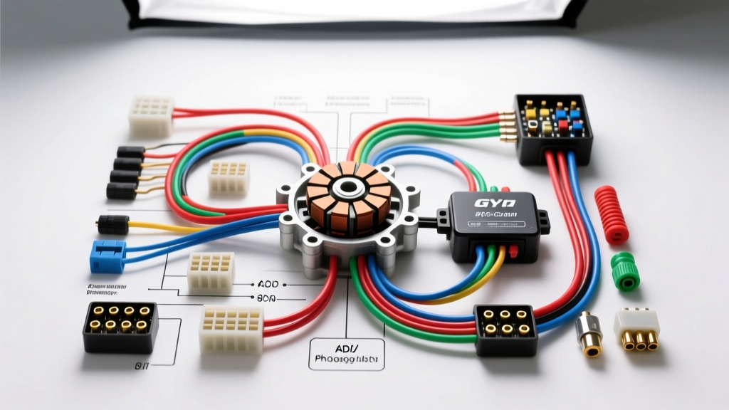
Introduction to GY6 Electrical Architecture
The GY6 engine platform is a ubiquitous 4-stroke, single-cylinder powerhouse found in countless 125cc, 150cc, and 250cc scooters, ATVs, go-karts, and dune buggies. Originally derived from Honda and Kymco engineering in the 1990s, the GY6 has since been cloned by dozens of overseas manufacturers. While the mechanical internals are remarkably robust, the electrical systems—particularly in modern clone variants—are notorious for poor grounding, undersized wire gauges, and confusing harness variations. Understanding the master GY6 engine wiring diagram is critical for diagnosing no-spark conditions, charging system failures, and starter interlock faults.
This advanced technical deep dive bypasses generic forum advice and provides exact pinout configurations, OEM wire color codes, AWG specifications, and multimeter testing parameters based on Kymco Global engineering standards and SAE J1128 low-voltage cable specifications.
The 8-Pin Magneto Stator: Output Specs & Wire Colors
The heart of the GY6 electrical system is the 8-pin magneto stator located behind the left-side crankcase cover. Unlike modern fuel-injected engines that rely on a single high-output 3-phase stator, the standard GY6 utilizes a split-coil design: one coil dedicated to ignition source voltage, one for AC lighting, and one for battery charging. Most clone harnesses use an 8-pin rectangular Molex-style connector, though only 5 to 6 wires are typically populated.
Stator Pinout and Multimeter Specifications
When diagnosing a dead battery or no-spark condition, you must test the stator at the engine-side harness plug (disconnected from the main wiring harness) using an AC voltmeter and an ohmmeter. Reference the table below for OEM specifications.
| Wire Color | Function | Resistance (Ohms) | AC Output @ 3000 RPM |
|---|---|---|---|
| Black/Red | Ignition Source Coil (CDI Feed) | 320 - 410 Ω | 85V - 110V AC |
| Blue/White (or Yellow/Red) | Pickup Coil (Trigger Signal) | 130 - 170 Ω | 0.5V - 2.0V AC Pulse |
| Yellow | AC Lighting Coil (Headlight) | 0.5 - 1.2 Ω | 24V - 32V AC |
| White | AC Charging Coil (Rectifier Feed) | 0.5 - 1.2 Ω | 24V - 32V AC |
| Green | Stator Ground (Engine Case) | < 0.5 Ω to Case | N/A |
Expert Insight: Many Chinese clone stators use 20 AWG wire for the internal windings to cut costs. This thin wire is highly susceptible to heat degradation. If your Yellow or White lighting/charging wires show continuity but output less than 20V AC at 3000 RPM, the internal winding insulation has likely melted and shorted to the stator core.
CDI Unit Deep Dive: AC vs. DC Ignition Modules
The Capacitor Discharge Ignition (CDI) unit is the most frequently replaced—and incorrectly replaced—component on a GY6 engine. The GY6 platform utilizes a 6-pin CDI connector (configured as a row of 4 pins and a row of 2 pins). There are two distinct types of CDI modules used across the platform: AC CDI and DC CDI. Installing the wrong unit will result in an immediate no-spark condition or severe electrical damage.
- AC CDI: Draws ignition power directly from the Black/Red stator source coil. It operates completely independently of the 12V battery. If the battery is dead, the scooter will still kick-start.
- DC CDI: Draws ignition power from the 12V DC battery circuit (via the ignition switch) and uses an internal voltage multiplier to charge the capacitor. It requires a healthy battery to fire the coil.
6-Pin CDI Connector Mapping
| Pin Position | Wire Color (Typical) | AC CDI Function | DC CDI Function |
|---|---|---|---|
| Row 1, Pin 1 | Green | Ground | Ground |
| Row 1, Pin 2 | Black/White or Red | Unused / NC | 12V DC Battery Power |
| Row 1, Pin 3 | Black/Yellow | Output to Ignition Coil | Output to Ignition Coil |
| Row 1, Pin 4 | Blue/White | Pickup Coil Signal | Pickup Coil Signal |
| Row 2, Pin 5 | Black/White | Kill Switch (Ground to Kill) | Kill Switch (Ground to Kill) |
| Row 2, Pin 6 | Black/Red | AC Source from Stator | Unused / NC |
Diagnostic Tip: To determine which CDI you have without opening the harness, check Pin 2 on the harness side with a multimeter. Turn the key to the 'ON' position. If Pin 2 reads 12V DC, you have a DC CDI system. If Pin 2 reads 0V, you have an AC CDI system.
Voltage Regulator/Rectifier (VRR) & Charging Circuit
The GY6 charging system relies on a shunt-style Voltage Regulator/Rectifier. The stator produces raw, unregulated AC voltage that fluctuates wildly with engine RPM. The VRR converts this AC to DC (rectification) and clamps the voltage at 14.2V - 14.8V (regulation) by dumping excess current from the White charging coil directly to ground.
Standard 4-pin VRR Pinout:
- Yellow Wire (x2): AC Input from Stator (Lighting & Charging coils tied together in some harnesses).
- Red Wire: Regulated 12V DC Output to Battery and Main Harness.
- Green Wire: Chassis Ground.
Critical Failure Mode: Because the GY6 VRR is a shunt-type regulator, never disconnect the battery while the engine is running. Without the battery acting as a massive capacitor to absorb voltage spikes, the VRR cannot dissipate the energy fast enough. The resulting 40V+ spike will instantly blow the headlight bulb, fry the DC CDI, and destroy the dash cluster LEDs. Always use a fully connected 12V battery when bench-testing a GY6 engine.
Starter Relay Logic and Safety Interlocks
The GY6 starter circuit is protected by a dual-safety interlock system designed to prevent the engine from cranking while the transmission is engaged or the kickstand is down. The starter solenoid (relay) requires two distinct signals to close the high-amperage contacts:
- 12V Power Feed: Routed from the ignition switch, through the brake light switches (front lever or rear pedal), and sometimes through a brake-engage relay.
- Ground Path: Provided by the kickstand switch (on street-legal scooters) or the left/right brake switch completing the circuit to the solenoid ground.
The main battery cables connecting the battery to the starter relay and the starter motor should be a minimum of 12 AWG stranded copper. Many budget ATVs use 14 AWG wire, which causes severe voltage drop under the 80-amp inrush current of the starter motor, leading to clicking solenoids and melted connectors.
Advanced Troubleshooting: Voltage Drop & Grounding
According to Haynes Motorcycle Manuals and standard automotive electrical diagnostics, 80% of all GY6 electrical gremlins stem from inadequate grounding. The engine cases are painted or powder-coated at the factory, creating a high-resistance barrier between the engine block and the steel frame.
The 'GY6 Ground Strap' Upgrade
Locate the main ground wire (usually Green, 16 or 18 AWG) bolted to the engine crankcase near the CVT cover. Perform a voltage drop test by placing your multimeter's black lead on the battery negative terminal and the red lead on the engine case while cranking. A reading above 0.2V indicates a ground fault.
The Fix: Fabricate a custom ground strap using 10 AWG or 12 AWG oxygen-free copper wire with heavy-duty ring terminals. Sand the paint off the engine case mounting bolt and the frame mounting point down to bare metal. Coat the terminals in dielectric grease after torquing to 10 Nm to prevent galvanic corrosion. This single upgrade resolves flickering headlights, weak spark at high RPM, and erratic gauge cluster behavior.
No-Spark Decision Tree
- Check Kill Switch: Verify 12V at the Black/White wire (Pin 5 on CDI) with the key ON and run switch engaged. If 0V, the kill switch is grounding the circuit.
- Check Pickup Coil: Backprobe the Blue/White wire at the CDI harness. Crank the engine. Look for a 0.5V - 2.0V AC pulse. If missing, check the air gap between the pickup coil and the flywheel magneto tab (spec: 0.5mm - 0.8mm).
- Check Ignition Coil: Disconnect the Black/Yellow wire from the ignition coil. Test for 12V DC (DC CDI) or high-voltage AC pulses (AC CDI) while cranking. If present but no spark, replace the ignition coil and spark plug cap (ensure the cap has a 5kΩ internal resistor).
By treating the GY6 not as a disposable appliance but as a precise electromechanical system, and by adhering to proper AWG sizing and pinout logic, you can eliminate the chronic electrical failures that plague this otherwise exceptional engine platform.