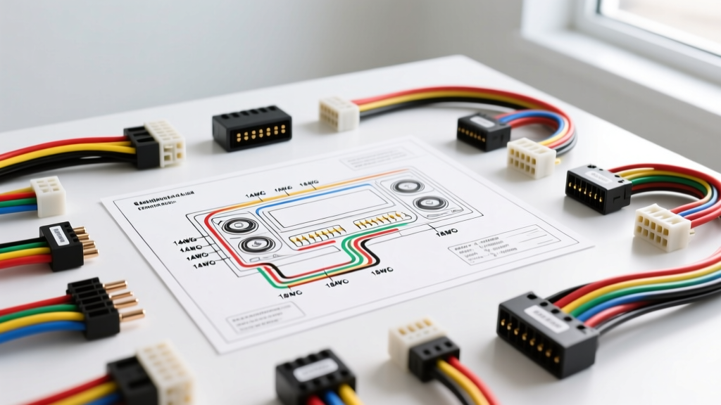
Introduction to Head Unit Wiring Fundamentals
Upgrading or replacing a factory stereo is one of the most common automotive electrical projects, yet it remains a primary source of frustration for beginners. The secret to a flawless installation lies in understanding how to read a car radio wiring diagram. Unlike complex ECU or CAN-bus schematics, head unit wiring relies on standardized, low-voltage direct current (DC) circuits. However, misinterpreting a single wire can lead to blown fuses, drained batteries, or permanently damaged internal amplifiers.
This beginner-friendly guide breaks down the universal standards of automotive audio wiring. We will cover the Consumer Technology Association (CTA) color codes, American Wire Gauge (AWG) requirements, ISO connector pinouts, and practical multimeter testing techniques to ensure your aftermarket installation is safe, reliable, and phase-aligned.
The CTA-2002 Standard Color Code Chart
To eliminate guesswork, the mobile electronics industry adopted the CTA-2002 standard (formerly CEA). This standard dictates specific wire jacket colors for aftermarket head units and wiring harness adapters. While factory OEM wiring varies wildly between a Ford, Toyota, or Volkswagen, the aftermarket harness you connect to the back of your new radio will almost always follow this universal color palette.
| Wire Color | Function | Circuit Type | Typical AWG |
|---|---|---|---|
| Yellow | Constant 12V+ (Battery) | Memory / High Current | 16 - 14 AWG |
| Red | Switched 12V+ (Ignition) | Accessory / Turn-On | 18 - 16 AWG |
| Black | Chassis Ground | Return Path | 16 - 14 AWG |
| Blue | Power Antenna / Amp Remote | Low Current Trigger | 18 AWG |
| Orange | Illumination / Dimmer | Variable Voltage (0-12V) | 22 - 18 AWG |
| White | Left Front Speaker (+) | Audio Signal | 18 AWG |
| White/Black Stripe | Left Front Speaker (-) | Audio Signal Return | 18 AWG |
| Gray | Right Front Speaker (+) | Audio Signal | 18 AWG |
| Gray/Black Stripe | Right Front Speaker (-) | Audio Signal Return | 18 AWG |
| Green | Left Rear Speaker (+) | Audio Signal | 18 AWG |
| Green/Black Stripe | Left Rear Speaker (-) | Audio Signal Return | 18 AWG |
| Purple | Right Rear Speaker (+) | Audio Signal | 18 AWG |
| Purple/Black Stripe | Right Rear Speaker (-) | Audio Signal Return | 18 AWG |
Power, Ground, and Memory Circuit Dynamics
A common beginner mistake is swapping the red and yellow wires. The yellow wire provides a constant 12V feed directly from the battery. It powers the radio's volatile memory (presets, clock, EQ settings) and supplies the main current for the internal amplifier when the unit is turned on. Because it handles the primary electrical load, it is typically a thicker 16 or 14 AWG wire.
The red wire is the switched accessory wire. It only receives 12V when the ignition key is in the 'ACC' or 'ON' position. Its primary job is to act as a low-current trigger to wake up the head unit's microprocessor. If you connect the yellow wire to a switched source and the red wire to a constant source, your radio will turn on and off with the key, but it will slowly drain your vehicle's battery over a few days due to the internal amplifier's standby current draw.
The black ground wire must be secured to bare, unpainted metal on the vehicle's chassis. Never ground a stereo to a seatbelt bolt or a plastic-backed dash bracket. A poor ground creates resistance, which manifests as alternator whine (a high-pitched noise that revs with the engine) or causes the head unit to shut off during heavy bass transients when current draw peaks.
Speaker Wire Identification and Phase Alignment
Under the CTA standard, speaker wires use a solid color for the positive (+) terminal and a matching color with a black tracer stripe for the negative (-) terminal. Maintaining correct speaker phase is critical. If you wire the left speaker out of phase (swapping positive and negative), the speaker cone will move inward while the right speaker moves outward. This acoustic cancellation results in a severe loss of mid-bass frequencies and a hollow, disjointed soundstage. Always verify phase using a dedicated speaker pop-tester or a digital multimeter set to DC voltage to observe the initial voltage spike direction when the battery is momentarily tapped.
Understanding ISO 10487 and Aftermarket Connectors
While many modern vehicles use proprietary, multi-pin proprietary connectors (requiring a vehicle-specific T-harness adapter from brands like Metra or Scosche), the international standard for automotive radio connections is ISO 10487. This standard divides the connection into two distinct blocks:
- Block A (Power & Control): An 8-pin connector handling battery, ignition, ground, illumination, and speed-sensitive volume inputs.
- Block B (Speaker Outputs): An 8-pin connector dedicated strictly to the four primary speaker channels.
Common ISO Block A Pinout Configuration
If you are building a custom harness or repairing a damaged factory plug, refer to this standard ISO Block A layout:
- Pin A1: Speed Signal (Mute/Volume adjust based on vehicle speed)
- Pin A2: Mute / Telephone Input
- Pin A3: Reserved / Auxiliary Input
- Pin A4: +12V Constant Battery (Fused at 10A-15A)
- Pin A5: Power Antenna / Amplifier Remote Turn-On (+12V out)
- Pin A6: Illumination / Dimmer (Variable voltage)
- Pin A7: +12V Switched Ignition (Accessory)
- Pin A8: Chassis Ground
For comprehensive vehicle-specific adapter guides and proprietary pinout translations, resources like the Crutchfield Car Stereo Wiring Guide provide invaluable model-by-model breakdowns that bridge the gap between OEM chaos and aftermarket standardization.
Step-by-Step: Verifying Wires with a Digital Multimeter
Never assume the factory wiring matches the diagram in your repair manual without physical verification. Factory harnesses can be modified by previous owners, or regional trim levels may use different pinouts. Follow this diagnostic sequence using a Digital Multimeter (DMM):
- Locate the Ground: Set your DMM to Continuity mode (the diode/beep symbol). Place the black probe on a known good chassis ground (like a metal dash brace). Probe the factory harness wires with the red probe. The wire that triggers the continuity beep is your Ground. Mark it immediately.
- Find Constant 12V (Memory): Turn the vehicle completely OFF and remove the key. Set the DMM to DC Voltage (20V scale). Place the black probe on your identified ground. Probe the remaining wires. The wire that reads ~12.4V to 12.6V with the key OFF is your Constant Battery wire.
- Find Switched 12V (Ignition): Keep the black probe on the ground. Turn the ignition key to the 'ACC' position. Probe the remaining unverified wires. The wire that suddenly jumps from 0V to ~12.4V is your Switched Accessory wire.
- Identify Illumination: Turn the vehicle's headlight switch to the 'ON' position. Probe the remaining wires. The wire that now shows 12V (or drops to a lower voltage if you rotate the dashboard dimmer wheel) is your Illumination/Dimmer wire.
Expert Troubleshooting: Real-World Installation Failures
Even with a perfect car radio wiring diagram, physical installation errors occur. Here is a diagnostic tree for the three most common beginner mistakes:
Symptom: The Radio Turns On, But There Is No Audio
Cause: Modern aftermarket head units feature an internal amplifier and a pre-amp RCA output stage. If your vehicle has a factory premium audio system (like Bose, JBL, or Harman Kardon), the factory wiring often uses differential (balanced) audio signals or low-impedance (2-ohm) speakers. Connecting standard 4-ohm aftermarket speakers to a factory amplified harness, or failing to bypass the factory amplifier, will result in severe distortion or total silence due to the head unit's internal short-circuit protection triggering.
Fix: Use an active line output converter (LOC) or a dedicated premium audio bypass harness that sends a turn-on signal to the factory amp while routing the audio correctly.
Symptom: The Head Unit Resets Every Time the Car Starts
Cause: The constant 12V (Yellow) and switched 12V (Red) wires are either swapped, or the constant wire is suffering from a voltage drop due to a corroded fuse tap or a poor crimp connection.
Fix: Verify the yellow wire at the back of the radio harness with a multimeter while a helper cranks the engine. If voltage drops below 9V during cranking, you have a high-resistance connection on the constant power feed. Re-crimp using a proper butt connector with heat shrink adhesive, or relocate the fuse tap to a higher-amperage constant circuit in the interior fuse box.
Symptom: High-Pitched Alternator Whine in the Speakers
Cause: A ground loop. This occurs when the head unit's ground and the external amplifier's ground are at slightly different electrical potentials, causing current to flow through the shield of the RCA cables.
Fix: Ensure both the head unit chassis ground and any external amplifier grounds are sanded down to bare, shiny metal and bolted securely to the exact same chassis cross-member or structural point to equalize the ground potential.