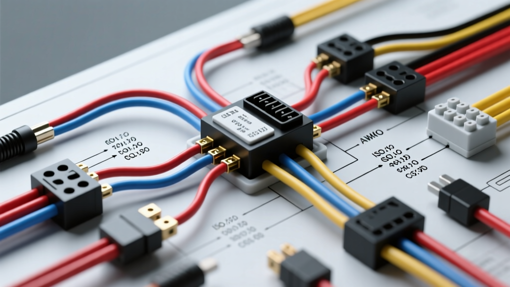
Upgrading Truck Exterior Lighting: Why You Need a Dedicated Harness
Adding auxiliary illumination to a truck or SUV requires more than simply splicing into the factory headlight harness. Modern vehicles utilize complex Body Control Modules (BCMs) and Pulse Width Modulation (PWM) circuits to manage exterior lighting. Drawing high amperage directly from these factory circuits will inevitably trigger diagnostic trouble codes (DTCs), cause BCM failure, or result in severe voltage drop. When consulting a wiring diagram for outside light installations, the primary objective is to isolate the high-current load from the vehicle's sensitive low-current switching circuits. This is achieved using a dedicated relay harness kit. A properly engineered harness ensures that your LED light bars, ditch lights, or camper shell exterior lamps receive full battery voltage while protecting the OEM wiring infrastructure from thermal overload and backfeeding.
Comparing Outside Light Wiring Harness Kits
Not all relay harnesses are created equal. The market is flooded with generic kits that use substandard PVC wire and low-grade electromechanical relays. For reliable exterior automotive applications, you must evaluate the wire jacket material, the relay type, and the connector quality. Below is a comparison matrix of the three primary harness architectures available for truck and SUV auxiliary lighting.
| Harness Type | Wire Jacket | Relay Technology | Best Application | Failure Risk |
|---|---|---|---|---|
| Generic Economy Kit | PVC (Standard) | Open-Frame Electromechanical | Low-draw LED pods (Under 10A) | High (UV degradation, corrosion) |
| Premium OEM-Style Kit | TXL (Cross-Linked) | Sealed ISO Mini Relay | LED Light Bars, Ditch Lights (15-20A) | Low (Excellent thermal/chemical resistance) |
| Smart CAN-Bus Harness | TXL / XLPE | Solid-State MOSFET Module | Modern Trucks with strict BCM monitoring | Very Low (No moving parts, built-in diagnostics) |
TXL (Thermoplastic Cross-Linked) wire is the industry standard for under-hood and exterior routing. As defined by the SAE J1128 Standard, TXL wire features a thinner insulation wall than standard PVC, allowing for better heat dissipation and flexibility in tight engine bays, while resisting automotive fluids, road salt, and high engine bay temperatures up to 125°C.
The Universal Wiring Diagram for Outside Light Setups
The foundation of almost all auxiliary exterior lighting is the standard 5-pin ISO 7588 mini relay (commonly referred to as a Bosch-style relay). Understanding the pinout is critical for interpreting any standard wiring diagram for outside light circuits. The relay acts as a heavy-duty remote switch, using a low-current trigger from the cab to close a high-current circuit directly from the battery.
ISO 5-Pin Relay Pinout Configuration
- Pin 30 (Battery +): Connected directly to the positive battery terminal via a primary inline fuse. This is the high-current source. Use Red 10 AWG or 12 AWG TXL wire.
- Pin 85 (Trigger +): Connected to the switched 12V source in the cab (e.g., upfitter switch, auxiliary switch bank, or tapped ignition source). Use Blue 18 AWG wire.
- Pin 86 (Ground / Trigger -): Connected to a clean, bare-metal chassis ground. In some factory headlight trigger setups, this pin receives the ground path from the OEM headlight circuit. Use Black 18 AWG wire.
- Pin 87 (Load +): The switched high-current output that routes to the positive terminal of the outside light assembly. Use Red 10 AWG or 12 AWG TXL wire.
- Pin 87a (Normally Closed): Not used in standard auxiliary lighting setups. It should be capped or left unconnected. Taping this pin is a common mistake that can lead to short circuits if the harness shifts.
According to Bosch Mobility Solutions, the coil circuit (Pins 85 and 86) draws approximately 150mA to 200mA, which is perfectly safe for most factory upfitter switches or BCM-tapped headlight circuits. However, if you are triggering the relay directly from a factory LED headlight wire, you must install a 1N4007 flyback diode across the relay coil to prevent inductive voltage spikes from damaging the vehicle's lighting control module.
Wire Gauge Selection and Voltage Drop Considerations
Selecting the correct American Wire Gauge (AWG) is critical for exterior lighting, especially on long-wheelbase trucks where the distance from the battery to the rear outside lights or roof rack can exceed 15 feet. Voltage drop causes LED drivers to flicker, halogen bulbs to burn yellow and dim, and relays to chatter due to insufficient coil voltage.
| Total Circuit Length (Out & Back) | Max Load: 10 Amps (LED Pods) | Max Load: 20 Amps (Light Bar) | Max Load: 30 Amps (Halogen Off-Road) |
|---|---|---|---|
| 0 - 10 Feet | 14 AWG | 12 AWG | 10 AWG |
| 10 - 15 Feet | 12 AWG | 10 AWG | 8 AWG |
| 15 - 20 Feet | 10 AWG | 8 AWG | 6 AWG |
Note: Total circuit length includes both the positive run to the light and the negative ground run back to the battery or chassis ground point.
For heavy-duty off-road applications, upgrading to 8 AWG for the main power feed (Pin 30 to Battery) ensures minimal voltage drop and provides a safety margin for future lighting upgrades. Always calculate voltage drop using the formula: VD = (2 x L x I x R) / 1000, where L is length in feet, I is current in amps, and R is wire resistance per 1000 feet. Aim to keep voltage drop below 3% of the system voltage (less than 0.36V on a 12V system).
Weatherproof Connector Selection for Exterior Routing
The most common failure point in any outside light installation is the connection at the light housing itself. Standard crimp connectors, twist-on wire nuts, and basic heat shrink will fail when exposed to road spray, pressure washing, and UV radiation. Professional automotive electricians rely on sealed connector systems to guarantee IP67 or IP69K water ingress protection.
- Deutsch DT Series: The gold standard for high-vibration, high-moisture environments. These thermoplastic housings use solid copper contacts and silicone rear seals. A 2-pin DT plug is ideal for single-color LED light bars, while a 3-pin DT is used for amber/white backlit ditch lights.
- TE Connectivity AMP Superseal 1.5: Excellent for routing harnesses through the firewall or connecting to relay blocks under the hood. They feature a secondary locking tab to prevent contact back-out.
- Adhesive-Lined Heat Shrink: When splicing is unavoidable, use 3:1 shrink ratio polyolefin tubing with an inner wall of thermoplastic adhesive. When heated, the adhesive melts and seals the wire strands, preventing capillary action from drawing moisture under the wire insulation.
Troubleshooting BCM Trigger and Ground Faults
Modern trucks (2015+ models from Ford, GM, and Ram) utilize smart junction boxes and BCMs that constantly monitor circuit resistance. If you tap a factory wire to trigger your outside light relay, the BCM may interpret the relay coil as a short circuit or a burnt-out bulb, shutting down the circuit entirely.
Symptom-Cause-Fix Decision Tree
- Symptom: Outside light turns on for one second, then shuts off; dash displays 'Check Exterior Lighting' warning.
Cause: BCM detects abnormal current draw (relay coil inrush current) and cuts power to protect the circuit.
Fix: Install a PWM filter module or use an opto-isolator relay harness. Alternatively, trigger the relay using a dedicated auxiliary switch bank (e.g., Ford Upfitter switches) that bypasses BCM monitoring. - Symptom: Relay clicks rapidly (chatters) but light does not illuminate or flickers wildly.
Cause: Severe voltage drop on the trigger wire (Pin 85) or a high-resistance ground on the coil (Pin 86).
Fix: Verify the trigger wire is not tapped into a PWM-modulated headlight circuit without a capacitor/diode filter. Ensure the coil ground is sanded to bare metal and secured with a star washer and anti-corrosion dielectric grease. - Symptom: Light stays on permanently, even when the ignition and switch are off.
Cause: Backfeeding through a shared ground circuit or a melted/welded internal relay contact.
Fix: Replace the ISO relay immediately. Test for backfeed by isolating the light's ground from the factory tail light ground; exterior auxiliary lights must have a dedicated, isolated chassis ground.
For comprehensive diagnostic procedures and relay load testing, technicians frequently refer to Littelfuse Automotive Relay Datasheets, which provide exact coil resistance and contact bounce specifications necessary for advanced multimeter diagnostics.
Final Routing and Loom Protection
Once the wiring diagram for outside light circuits is executed, proper physical protection is mandatory. Route all under-hood wiring away from exhaust manifolds, steering shafts, and the radiator fan shroud. Secure the harness every 12 inches using UV-resistant nylon cable ties or stainless steel P-clamps with rubber cushions. Encase the main harness runs in split-loom corrugated tubing or, for a cleaner OEM appearance, braided PET expandable sleeving. Where the harness passes through the firewall or body panels, always use a rubber grommet and apply silicone sealant to prevent water intrusion and exhaust fumes from entering the cabin. By adhering to these professional standards, your auxiliary exterior lighting will operate flawlessly for the lifespan of the vehicle.