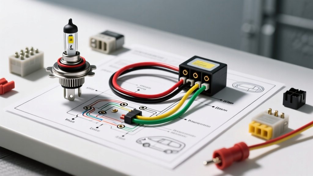
Why Factory Headlight Sockets Fail During Upgrades
Upgrading your vehicle's lighting system is one of the most impactful modifications you can perform, but it frequently exposes the weaknesses of factory wiring. When installing high-wattage halogen bulbs (e.g., 100W/80W) or poorly heat-sinked LED conversions, the factory H4 (9003) headlight socket is often the first component to fail. Standard OEM sockets are molded from PBT (polybutylene terephthalate) plastic, which begins to soften and melt at temperatures exceeding 160°C. Furthermore, factory wiring is typically 16 or 18 AWG, designed only for the 55W/60W draw of stock halogen bulbs. Pushing higher amperage through these thin wires causes severe voltage drop, generating excess heat at the terminal crimps and resulting in the infamous 'melted socket' scenario.
To properly execute a lighting upgrade, you must bypass the factory power delivery system using a heavy-duty relay harness. This guide details the exact H4 headlight socket wiring diagram, pinout configurations, and the step-by-step relay modification required to safely power modern LEDs or high-output halogens while preserving your factory headlight switch.
The H4 (9003) Headlight Socket Wiring Diagram & Pinout
The H4 bulb (also known as 9003 or HB2 in certain markets) utilizes a standard 3-prong connector. Understanding the physical layout and electrical function of each pin is critical before cutting into your factory harness. According to Hella Automotive Lighting technical documentation, the H4 standard dictates a specific ground and dual-filament trigger configuration.
Pin Configuration and Wire Color Standards
| Pin Position (Front View) | Function | OEM Wire Color (Typical) | Aftermarket Relay Wire |
|---|---|---|---|
| Pin 1 (Left / Horizontal) | Ground (-) | Black or White/Black | Black |
| Pin 2 (Top / Vertical) | Low Beam (+) | Red/White or Green | Red |
| Pin 3 (Right / Diagonal) | High Beam (+) | Blue or Yellow | Yellow |
Note: Japanese domestic market (JDM) vehicles occasionally reverse the Low and High beam pin assignments compared to US/EU specifications. Always verify your specific vehicle's headlight socket wiring diagram with a multimeter before making permanent connections.
Upgrade Project: Installing a Heavy-Duty Relay Harness
The core of this modification involves using the factory H4 plug merely as a low-amperage trigger signal. The actual current required to power the new headlights will be drawn directly from the battery via a relay. This ensures the new ceramic H4 socket receives a full 12.5V+ without overloading the factory headlight switch or thin gauge wiring.
Step-by-Step Relay Harness Wiring
- Remove the Factory Socket: Cut the factory H4 plug off the harness, leaving at least 6 inches of wire for splicing. Strip the wires and solder them to the trigger wires of your new relay harness. Use adhesive-lined polyolefin heat shrink tubing to seal the connections against moisture and corrosion.
- Wire the Relay (DIN 72552 Standard): Most automotive upgrades use a standard Bosch-style 4-pin relay. As outlined in the 12 Volt Planet relay guide, the terminals are numbered as follows:
- Terminal 86 (Trigger): Connect to the factory Low Beam or High Beam positive wire.
- Terminal 85 (Ground): Connect to a clean, bare-metal chassis ground or the factory Ground wire.
- Terminal 30 (Power In): Connect directly to the positive battery terminal via an inline MAXI fuse (rated 15A for LEDs, 20A for 100W halogens).
- Terminal 87 (Power Out): Connect to the positive pin of your new heavy-duty ceramic H4 socket.
- Ground the New Socket: Run a dedicated 12 AWG ground wire from the new ceramic socket's ground pin directly to the chassis or battery negative. Do not rely on the factory ground wire, as it may suffer from ground loop interference or voltage drop.
Wire Gauge & Connector Specifications for Headlight Mods
When building a custom headlight socket wiring diagram from scratch, selecting the correct wire gauge is non-negotiable. Adhering to SAE J1128 standards for low-tension primary automotive cable ensures your harness can handle the thermal load of the engine bay. For high-temperature environments, always specify TXL (Thin-wall Cross-linked) or GXL wire rather than standard PVC wire, as TXL is rated for continuous operation at 125°C.
| AWG Size | Max Ampacity (Engine Bay) | Recommended Application |
|---|---|---|
| 18 AWG | 6 Amps | Relay trigger signals, CANBUS decoders |
| 14 AWG | 15 Amps | Standard LED headlight power feeds |
| 12 AWG | 20 Amps | 100W Halogen upgrades, High beam circuits |
| 10 AWG | 30 Amps | Main battery feed to relay block (Terminal 30) |
Crimping vs. Soldering the Socket
While soldering is excellent for joining wires, the connection point at the headlight socket itself should utilize high-quality, open-barrel or closed-barrel crimps. Solder can become brittle under the extreme vibration of the front fascia and engine harmonics, leading to micro-fractures. Use a proper ratcheting crimp tool to compress the terminals onto the 14 or 12 AWG wire, then slide the socket into a new ceramic H4 housing. Ceramic is completely impervious to the heat generated by high-wattage bulbs and will never melt or deform.
Troubleshooting Common Headlight Upgrade Issues
Even with a perfect headlight socket wiring diagram, modern vehicle electronics can introduce complications during an upgrade. Here is how to diagnose the most common issues encountered during LED and relay harness installations.
1. LED Flickering or Strobe Effect (CANBUS/PWM Issues)
Symptom: The newly installed LED headlights flicker rapidly when the engine is running, or the vehicle's dashboard throws a 'Bulb Out' warning.
Cause: Many modern vehicles (especially Chrysler, Jeep, Dodge, and newer European models) use Pulse Width Modulation (PWM) to control the low-beam circuit for Daytime Running Lights (DRL). Instead of sending a steady 12V, the ECU pulses the voltage rapidly. While halogen filaments are too slow to react to this, LED drivers interpret it as rapid on/off signals.
Fix: Install a PWM decoder or anti-flicker capacitor module inline between the factory trigger wire and Terminal 86 of your relay. This capacitor smooths the pulsed signal into a steady voltage, allowing the relay to engage cleanly without chatter.
2. High Beam Indicator Light Stays On (Backfeeding)
Symptom: The blue high-beam indicator on the dashboard remains illuminated even when the headlights are turned off or set to low beam.
Cause: In some dual-relay setups (one relay for low beam, one for high beam), current can backfeed through the dashboard indicator bulb or the factory multifunction switch, tricking the high-beam relay into staying energized.
Fix: Install a 1N4001 diode on the trigger wire (Terminal 86) of the high-beam relay. The diode acts as a one-way valve, allowing the factory switch to trigger the relay but blocking any reverse current from backfeeding into the circuit.
3. Voltage Drop at the Socket
Symptom: Headlights appear dim, and a multimeter reads less than 12.0V at the ceramic socket pins while the engine is running.
Cause: Undersized main power wire, poor chassis ground, or corroded inline fuse holders.
Fix: Perform a voltage drop test. Place your multimeter's positive probe on the battery positive terminal and the negative probe on the socket's positive pin. A reading above 0.2V indicates excessive resistance. Upgrade the main power feed to 10 AWG and ensure all ground points are sanded down to bare, shiny metal before securing with a star washer and zinc-plated bolt.
Final Inspection and Weatherproofing
Once your H4 headlight socket wiring diagram is fully implemented and tested, the final step is environmental protection. The engine bay is a hostile environment filled with water, road salt, and extreme thermal cycling. Coat all exposed relay terminals with dielectric grease to prevent galvanic corrosion. Wrap the entire harness in split-loom tubing or, preferably, Tesa cloth tape to mimic OEM harness styling and prevent the wires from chafing against the radiator support or strut towers. By upgrading to a ceramic socket and a direct-battery relay harness, you ensure your lighting modification remains safe, bright, and reliable for the life of the vehicle.