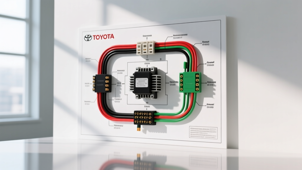
The Denso 3-Pin Alternator Architecture
When diagnosing charging system failures on classic and late-model Toyota vehicles, understanding the Toyota 3 pin alternator wiring diagram is critical. Widely utilized by Denso in 1980s, 1990s, and early 2000s Toyota trucks, 4Runners, Camrys, and Land Cruisers, this 3-pin connector bridges the gap between the vehicle’s ignition switch, the dashboard indicator, and the battery’s actual state of charge. Unlike modern LIN-bus controlled alternators, this analog system relies on distinct voltage pathways to regulate field current and monitor system health.
From a cost and tooling perspective, repairing this harness is highly accessible for DIY mechanics, provided you have the correct terminal extraction tools and understand the strict wire gauge requirements. A misdiagnosis here often leads to unnecessary alternator replacements, costing hundreds of dollars in wasted parts. Below, we break down the exact OEM specifications, the specialized tools required for a factory-grade repair, and a comprehensive cost analysis comparing DIY harness rebuilding versus dealership replacement.
OEM Pinout and Wire Gauge Specifications
The Denso 3-pin connector relies on three distinct circuits. Using the wrong wire gauge—particularly on the Sense (S) circuit—will introduce voltage drop, causing the internal voltage regulator to overcompensate and overcharge the battery. The following table outlines the standard specifications derived from the Toyota Technical Information System (TIS) and standard SAE International J1113 Electrical Standards.
| Terminal | Function | Typical OEM Wire Color | Required AWG | Voltage / Signal State |
|---|---|---|---|---|
| IG | Ignition Power | Black/Red or Black/Orange | 16 AWG | 12V+ (Key ON, Engine OFF) |
| L | Charge Indicator Lamp | Yellow or Green | 18 AWG | 0V (Charging) / 12V (Not Charging) |
| S | Battery Voltage Sense | White or Red | 12 AWG or 14 AWG | Direct Battery Voltage (Max 0.2V drop) |
| B+ | Main Charging Output | Red (Heavy Cable) | 8 AWG or 6 AWG | 13.5V - 14.5V (Engine Running) |
Note: Wire colors can vary slightly depending on the exact model year and chassis code. Always cross-reference with a Haynes Toyota Repair Manual for your specific vehicle before cutting or splicing.
Tool Requirements for Accurate Diagnosis
Testing the Toyota 3-pin system requires more than a basic test light. Because the Sense (S) wire measures voltage drop in millivolts, and the Lamp (L) wire utilizes a pulse-width modulated or low-current DC signal to illuminate the dash bulb, using the wrong diagnostic equipment can lead to false conclusions or damage the delicate weather seals on the Denso connector.
Essential Diagnostic Equipment
- True-RMS Digital Multimeter (DMM): Required for measuring the voltage drop across the Sense wire. A standard auto-ranging meter with at least 10 megohms of input impedance is necessary to avoid drawing parasitic current through the sensing circuit.
- Back-Probe Pins: Never pierce the wire insulation with a T-pin to test the 3-pin connector. Piercing introduces moisture into the copper strands, leading to green corrosion and eventual open-circuit failures. Use dedicated insulated back-probes to test the terminals from the rear of the connector housing.
- Inductive Clamp Ammeter: Used to measure the B+ output without disconnecting the main 8 AWG charging cable, allowing for dynamic load testing (e.g., turning on headlights, A/C, and rear defroster simultaneously).
Specialized Wiring and Extraction Tools
If the connector housing is melted, brittle, or the terminals are corroded, you must replace the pigtail. The Denso 3-pin connector utilizes specific female terminals with weather seals. To perform a professional repair, you need:
- Terminal Extraction Tool: A dual-prong or specialized single-prong depressor designed for Denso/Sumitomo housings. Attempting to pry terminals out with a flathead screwdriver will destroy the plastic locking tangs inside the connector cavity.
- Open-Barrel Crimpers: OEM Denso terminals use open-barrel crimps. Standard insulated terminal crimpers will crush the terminal improperly, leading to high resistance. Invest in a ratcheting open-barrel crimper (such as the Titan 11520 or equivalent) to ensure a gas-tight crimp on the 12-18 AWG wires.
- Adhesive-Lined Heat Shrink: Used over the B+ ring terminal and any splices to prevent moisture ingress and resist under-hood thermal cycling.
Cost Analysis: DIY Repair vs. Dealership Service
When a Toyota 3-pin alternator harness fails, the symptoms (dimming lights, dead battery, illuminated charge lamp) often mimic a bad alternator. Dealerships will frequently recommend replacing the entire alternator and the associated engine harness if they detect melted pins, resulting in a massive invoice. By isolating the failure to the 3-pin pigtail and repairing it yourself, the cost savings are substantial.
Material and Labor Breakdown
| Item / Service | DIY Cost (Estimate) | Dealership Cost (Estimate) | Notes |
|---|---|---|---|
| Alternator (Denso Reman) | $130 - $180 | $350 - $550 (OEM New) | Dealerships rarely use aftermarket remanufactured units. |
| 3-Pin Connector Pigtail | $15 - $25 | $60 - $90 | Aftermarket pigtails are widely available and reliable. |
| Wiring & Terminals | $20 - $35 | N/A (Billed in Labor) | Includes 12 AWG wire, open barrel terminals, heat shrink. |
| Labor (2.5 Hours @ $160/hr) | $0 (Your Time) | $400 | Dealership flat-rate time for harness repair and testing. |
| Total Estimated Cost | $165 - $240 | $810 - $1,040 | DIY saves up to $800 by avoiding dealership markup and labor. |
Real-World Failure Modes and Diagnostic Matrix
Before spending money on parts, use your DMM to run through this diagnostic matrix. These are the most common failure modes specific to the Toyota 3-pin Denso system.
Symptom 1: Battery Overcharging (15.0V+ at Battery)
- Cause: Open circuit or high resistance in the S (Sense) wire. If the voltage regulator cannot 'see' the actual battery voltage, it defaults to an internal fallback mode, measuring voltage directly at the alternator casing. This causes it to push maximum voltage to overcome perceived wire resistance.
- Fix: Perform a voltage drop test on the White/Red Sense wire from the alternator plug to the positive battery terminal. If the drop exceeds 0.2V with the engine running and accessories on, repair the wire or replace the pigtail. Do not just replace the alternator; the new one will also overcharge if the Sense wire is broken.
Symptom 2: Dash Charge Lamp Stays ON, but Battery is at 14.2V
- Cause: Short to ground on the L (Lamp) wire, or a failing internal voltage regulator ground path. The L wire provides the initial excitation current. If it is shorted, the dash bulb receives constant ground, keeping it illuminated.
- Fix: Disconnect the 3-pin connector. Turn the key to the ON position. If the dash light goes out, the short is inside the alternator (requires regulator replacement). If the dash light stays on with the connector unplugged, the short to ground is in the chassis wiring harness between the dash and the alternator.
Symptom 3: Alternator Not Charging Until Engine is Revved to 2500+ RPM
- Cause: Loss of initial excitation current. This happens if the L wire is broken, or if the dashboard charge indicator bulb is burnt out. The Denso regulator relies on the resistance of the dash bulb to complete the initial rotor excitation circuit.
- Fix: Check the dash bulb first. If the bulb is good, back-probe the L terminal at the alternator with the key ON. You should see roughly 2V to 4V (the voltage drop across the bulb). If you see 0V, trace the L wire back to the instrument cluster for an open circuit.
Best Practices for Long-Term Reliability
When rebuilding the Toyota 3 pin alternator wiring harness, environmental sealing is your primary defense against future failures. The Denso connector sits low in the engine bay, exposed to road splash, oil mist, and extreme heat from the exhaust manifold. Always pack the rear of the connector cavity with dielectric grease before inserting the newly crimped terminals. This prevents capillary action from drawing moisture into the wire strands. Furthermore, ensure the B+ 8 AWG ring terminal is torqued to the alternator output stud to exactly 10-12 Nm (7.4-8.9 lb-ft). An under-torqued B+ nut will arc under heavy electrical loads, melting the plastic insulator cover and destroying the newly installed harness.