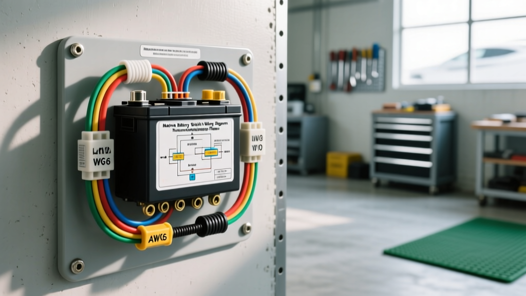
Introduction to Marine Battery Disconnect Systems
When integrating heavy-duty marine battery switches into expedition vehicles, overland trucks, or dedicated marine vessels, the wiring architecture must adhere to strict ABYC (American Boat and Yacht Council) and SAE J1171 standards. Unlike standard automotive rotary switches, marine-grade isolators like the Blue Sea Systems 9001e are designed to handle extreme cranking amperages and resist corrosive saltwater or high-humidity environments. However, improper wiring, inadequate crimping, or failing Alternator Field Disconnect (AFD) circuits can lead to catastrophic voltage drops, arcing, or blown alternator diodes. This guide provides a comprehensive step-by-step troubleshooting flow and wiring diagram reference for diagnosing and rectifying faults in a marine battery switch circuit.
Core Wiring Diagram & Component Specifications
Before initiating the troubleshooting flow, verify that your physical installation matches the baseline marine wiring schematic. The primary positive circuit should utilize tinned, stranded copper wire (ABYC Type 3) to prevent black-wire corrosion. The main positive feed runs from the battery bank positive terminal to the 'C' (Common) stud on the battery switch, while the '1' or '2' stud routes to the main DC distribution busbar or starter solenoid.
| Component / Spec | Blue Sea 9001e (Standard) | Blue Sea 9002e (HD) | ABYC Compliance Note |
|---|---|---|---|
| Continuous Rating | 350 Amps | 600 Amps | Must exceed max continuous DC load |
| Cranking Rating (10s) | 1200 Amps | 2000 Amps | Must exceed starter motor peak draw |
| Recommended Wire (Up to 5ft) | 2/0 AWG Tinned | 4/0 AWG Tinned | Max 3% voltage drop combined |
| Recommended Wire (5-10ft) | 4/0 AWG Tinned | 2x 4/0 AWG Tinned | Up-size for extended cable runs |
| Stud Size / Material | 3/8 inch Tin-Plated | 1/2 inch Tin-Plated | Stainless steel nuts required |
| Terminal Torque Spec | 120 in-lbs (13.5 Nm) | 240 in-lbs (27.1 Nm) | Do not exceed to avoid cracking casing |
Step-by-Step Troubleshooting Decision Tree
Use the following diagnostic flow to isolate electrical faults. Ensure your digital multimeter (DMM) is set to DC Volts for Phase 1 and DC Millivolts (mV) for Phase 2.
Phase 1: Complete Power Loss (Zero Voltage at Busbar)
Symptom: The switch is rotated to the 'ON' position, but the DC distribution busbar shows 0.0V, and the vessel or vehicle has no accessory power.
- Check Battery Voltage: Measure directly across the battery bank terminals. If reading is below 11.5V, charge or replace batteries before proceeding.
- Measure Switch Input (C Stud): Place the DMM positive lead on the 'C' stud nut and negative lead on the battery negative busbar. If 0.0V, the main positive feed is severed or the main battery fuse (e.g., Class T or ANL) is blown.
- Measure Switch Output (1 or 2 Stud): Place the positive lead on the output stud. If battery voltage is present here but not at the busbar, the fault lies in the feed cable between the switch and the busbar.
- Internal Contact Failure: If input voltage is present but output is 0.0V with the switch engaged, the internal copper contacts are burned or the mechanical detent has failed. Replace the switch immediately.
Phase 2: Severe Voltage Drop Under Cranking Load
Symptom: The engine cranks sluggishly, or the switch casing becomes hot to the touch during high-amperage draws (winching, bow thrusters, or engine starting).
- Perform Millivolt Drop Test: Set DMM to DC mV. Connect the leads directly to the metal studs of the switch (not the nuts or lugs) to measure the voltage drop exclusively across the internal contacts.
- Apply Load: Engage the starter motor or heavy DC load. A healthy Blue Sea 9001e should show a voltage drop of less than 0.02V (20mV). If the drop exceeds 0.10V (100mV), internal resistance is critically high.
- Inspect Terminal Connections: If the drop across the studs is acceptable, but the drop across the cable lugs and nuts is high, you have a poor crimp or a loose connection. Verify torque specs (120 in-lbs for 3/8" studs).
- Check Crimp Integrity: Marine environments demand hex-crimped lugs using a hydraulic or heavy ratcheting crimper. Indent crimps often fail under marine vibration profiles. Re-crimp using a 3:1 adhesive-lined marine heat shrink (e.g., 3M MDT) to seal out moisture.
Phase 3: Alternator Diode Failure (The AFD Circuit)
Symptom: The battery switch was accidentally turned to 'OFF' while the engine was running, resulting in a dead alternator and blown diodes. Alternatively, the alternator fails to excite upon startup.
Marine wiring diagrams utilize an Alternator Field Disconnect (AFD) to protect the alternator. The AFD is a secondary micro-switch inside the main battery isolator that cuts power to the alternator's voltage regulator/field wire before the main heavy-duty contacts separate, preventing the inductive voltage spike that destroys diodes.
- Verify AFD Wiring: The AFD terminal on the switch should be wired in series with the alternator's ignition/excitation wire (typically 16 AWG Pink wire per ABYC standards).
- Test AFD Continuity: With the switch OFF, measure continuity between the AFD terminal and the common ground or input (depending on switch model logic). There should be an open circuit. When switched ON, continuity should be established.
- Trace the Field Wire: If the alternator is not charging despite the main switch being ON, use a test light or DMM to verify 12V is reaching the alternator's 'F' or 'IG' terminal. If not, trace the 16 AWG Pink wire back to the AFD terminal and check for blown inline fuses (typically 5A or 10A AGC glass fuses).
Common Wiring Mistakes and Failure Modes
- Stacking Lugs: ABYC standards strictly prohibit stacking more than four lugs on a single stud. If you need to connect a starter cable, a windlass cable, and a DC busbar feed, utilize a heavy-duty marine busbar rather than stacking them on the battery switch output stud.
- Using Automotive Wire: Standard automotive CCA (Copper Clad Aluminum) or untinned copper wire will rapidly oxidize in marine or humid overland environments. The green corrosion creates immense resistance, leading to localized heating and potential fire hazards.
- Missing Ignition Protection: If the battery switch is mounted in an enclosed engine bay or bilge area where explosive gasoline vapors may accumulate, the switch must be SAE J1171 ignition protected. Standard rotary switches can arc internally and ignite fumes.
Authoritative Reference Sources
For advanced schematic details, torque matrices, and compliance codes, consult the following authoritative marine electrical resources:
- Blue Sea Systems Installation & Troubleshooting Wizard - Comprehensive guide to 9000-series switch logic and AFD wiring.
- ABYC E-11 AC & DC Electrical Systems on Boats - The definitive standard for marine wire color codes, ampacity tables, and voltage drop limitations.
- SAE J1171 Marine Electrical Standard - Specifications for ignition protection and salt-spray corrosion resistance in marine electrical components.