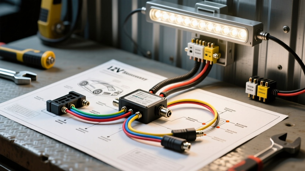
Automotive vs. Residential: Adapting the Diagram of Wiring a Light Fixture
When homeowners search for a diagram of wiring a light fixture, they are typically dealing with 120V AC alternating current, wire nuts, and standard Romex cabling. However, in the automotive and off-road truck world, wiring an auxiliary light fixture—such as an LED light bar, fog lamps, or rally lights—requires an entirely different approach. You are dealing with a 12V DC (nominal 14.4V when the alternator is running) environment where high amperage, vibration, and moisture resistance are paramount.
Connecting a high-draw off-road light fixture directly to your truck's factory headlight switch or upfitter circuit is a guaranteed way to overload the OEM wiring harness, melt the switch contacts, or cause an electrical fire. To do this safely, we use a standard ISO Mini 4-pin relay (often called a Bosch-style relay). This guide provides a beginner-friendly, expert-level breakdown of how to wire an automotive light fixture using a relay, ensuring your auxiliary lighting is reliable, safe, and capable of handling harsh environmental conditions.
The Core Diagram of Wiring a Light Fixture to a 4-Pin Relay
The standard ISO Mini relay acts as a remote-controlled heavy-duty switch. It allows a low-current circuit (your dashboard switch or factory headlight trigger) to safely control a high-current circuit (the power drawn directly from the battery to your light fixture). Below is the fundamental pinout mapping for the 4-pin relay harness.
Pin 30: Main Power Input (High Current)
Pin 30 is the common terminal that receives 12V+ directly from the vehicle's battery. This wire must be routed through an inline fuse holder placed as close to the battery positive terminal as possible (ideally within 8 inches). According to Littelfuse Automotive Circuit Protection guidelines, the fuse must be rated slightly higher than the maximum continuous draw of the light fixture but lower than the ampacity of the wire used.
Pin 87: Power Output to Fixture (High Current)
Pin 87 is the Normally Open (NO) contact. When the relay coil is energized, the internal electromagnet pulls the contact arm closed, allowing high current to flow from Pin 30 to Pin 87. This wire routes directly to the positive input of your auxiliary light fixture.
Pin 85: Coil Ground (Low Current)
Pin 85 completes the low-current control circuit. It must be securely grounded to the vehicle's bare metal chassis or tied back to the battery's negative terminal. A poor ground here is the number one cause of relay chatter and dim auxiliary lights.
Pin 86: Coil Trigger / Switched 12V+ (Low Current)
Pin 86 receives the 12V+ trigger signal. This can be wired to an OEM upfitter switch, an aftermarket toggle switch fed by an ignition-on fuse, or spliced into the factory high-beam wire using a Posi-Tap or T-tap connector to trigger the light bar automatically when the high beams are engaged.
Wire Gauge (AWG) and Fuse Sizing Specifications
Selecting the correct wire gauge is critical. Automotive wire must conform to SAE J1128 Low-Tension Primary Cable standards, which account for the high-temperature environments found under the hood of a truck. Do not use residential THHN wire; it lacks the chemical resistance to oil, coolant, and road salts required for vehicle wiring.
| Fixture Wattage | Amperage Draw (at 14.4V) | Minimum AWG Wire (Main) | Minimum AWG (Trigger) | Max ATO/ATC Fuse |
|---|---|---|---|---|
| 50W - 100W | 3.5A - 7.0A | 14 AWG | 18 AWG | 10A |
| 120W - 240W | 8.3A - 16.6A | 12 AWG | 16 AWG | 20A |
| 300W - 480W | 20.8A - 33.3A | 10 AWG | 16 AWG | 40A |
| 500W+ | 34.7A+ | 8 AWG | 14 AWG | 50A (Use MAXI) |
Choosing the Right Connectors: Weather-Pack vs. Deutsch DT
A standard diagram of wiring a light fixture for home use ignores moisture. In automotive applications, water ingress leads to galvanic corrosion, increased resistance, and eventual circuit failure. When terminating the wires to your LED light fixture, abandon standard butt-splices and electrical tape.
- Deutsch DT Connectors: The industry standard for off-road lighting. These IP68-rated connectors use solid copper contacts crimped with a specialized tool, sealed with silicone grommets and wedges. They are entirely waterproof and vibration-proof.
- Adhesive-Lined Heat Shrink: If you must splice or extend wires, use dual-wall, adhesive-lined marine-grade heat shrink. When heated, the inner wall melts and bonds to the wire insulation, creating a watertight seal that prevents capillary action from drawing moisture under the insulation.
- Ring Terminals for Grounds: Never use fork terminals or bare wire wrapped around a bolt for chassis grounds. Use a closed-ring terminal crimped over the stripped wire, secured with a stainless steel bolt, star washer, and nut. The star washer bites through the paint to ensure bare metal-to-metal conductivity.
Understanding Voltage Drop in 12V DC Systems
Unlike 120V AC home wiring, a 12V DC system is highly sensitive to voltage drop. If your light fixture requires 14.4V to operate at peak lumens, but your undersized wiring and poor crimps introduce 3 volts of resistance, the fixture will only see 11.4V. This results in dim output, flickering, and excessive heat generation in the wires.
To mitigate voltage drop, always route the main power and ground wires together in the same loom to prevent inductive interference, and keep the total length of the high-current circuit (Pin 30 to Pin 87 to Fixture to Ground) as short as physically possible. If routing 15 feet of wire to the rear of a truck bed for chase lights, bump your wire gauge up by one size (e.g., use 10 AWG instead of 12 AWG) to compensate for the distance.
Step-by-Step Routing and Termination Guide
- Disconnect the Battery: Always remove the negative battery terminal before beginning any automotive electrical work to prevent short circuits.
- Mount the Relay: Secure the relay in a dry, elevated location within the engine bay. Use a relay harness bracket bolted to an existing fender bolt. Never zip-tie a relay directly to a hot radiator hose or exhaust manifold.
- Run the Main Power: Route the 12 AWG Red wire from the battery to Pin 30. Install the inline ATO fuse holder within 8 inches of the battery terminal, but leave the fuse out until the entire job is complete.
- Wire the Trigger: Run the 16 AWG Blue wire to your cabin switch or OEM upfitter switch output. Use a rubber grommet when passing through the vehicle firewall to prevent the metal from slicing the wire insulation over time.
- Establish the Grounds: Sand a 1-inch circle of paint off the chassis down to bare steel. Bolt down your Pin 85 ground wire and the light fixture's negative ground wire using star washers. Coat the finished connection in dielectric grease to prevent oxidation.
- Test and Seal: Reconnect the battery, insert the fuse, and test the fixture. Once confirmed operational, wrap all harnesses in corrugated split-loom tubing or Tesa cloth tape to protect against abrasion and engine bay heat.
Common Automotive Wiring Mistakes and Troubleshooting
Even with a perfect diagram of wiring a light fixture, mistakes happen. If your auxiliary lights fail to turn on, use a digital multimeter (DMM) to diagnose the circuit systematically:
- Symptom: Relay clicks, but lights stay off.
Diagnosis: The low-current coil circuit (Pins 85/86) is working, but the high-current circuit is failing. Check the main fuse at the battery. Probe Pin 30 with your DMM (set to DC Volts); it should read 12.6V+. If it reads 0V, you have a break in the main power wire. If Pin 30 has power but Pin 87 does not when engaged, the internal relay contacts are burnt or defective. - Symptom: Lights flicker at idle but brighten when revving.
Diagnosis: Severe voltage drop or a bad ground. The alternator is pushing higher voltage at higher RPMs, overcoming the resistance. Clean your chassis grounds and verify you are using the correct AWG wire size. - Symptom: Lights stay on after the truck is turned off.
Diagnosis: Backfeeding. If you triggered Pin 86 using a diode-less splice into a circuit that remains hot (like a parking light circuit), voltage is backfeeding into the relay coil. Install a 1N4001 flyback diode across Pins 85 and 86 (stripe facing Pin 86) to prevent voltage spikes and backfeed issues.
By adhering to these automotive-specific standards and utilizing the correct relay diagram, your auxiliary light fixture will provide reliable, high-output illumination for years, regardless of the terrain or weather conditions you encounter. For further certification standards on automotive electrical repair, consult resources from the National Institute for Automotive Service Excellence (ASE).