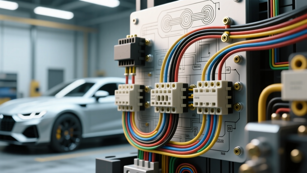
Introduction: The Hidden Dangers of Terminal Block Schematics
When fabricating custom harnesses, installing aftermarket ECU breakout boxes, or troubleshooting heavy-duty power distribution modules, interpreting a wiring diagram terminal block layout is a foundational skill. However, terminal blocks—whether they are TE Connectivity DEUTSCH bulkhead connectors, Bosch Motronic ECU interfaces, or Bussmann power distribution blocks—are unforgiving of errors. A single misread cavity number or mismatched wire gauge can result in catastrophic short circuits, fried powertrain control modules (PCMs), or severe electrical fires. This guide details the most critical safety warnings and common mistakes technicians make when working with automotive terminal blocks.
Critical Safety Warnings Before Touching the Block
Before you strip a single wire or insert a terminal pin, you must adhere to strict automotive electrical safety protocols. Modern vehicles operate with highly sensitive low-voltage CAN bus networks and high-current power feeds sharing the same bulkhead.
- Capacitor Discharge Wait Time: Disconnecting the negative battery terminal is not enough for modern ECUs and hybrid inverter systems. You must wait a minimum of 10 to 15 minutes after battery disconnect to allow internal PCM capacitors to discharge. Probing a terminal block with a multimeter or inserting a live pin before discharge can arc and destroy the ECU's internal logic board.
- The Dielectric Grease Myth: A pervasive and dangerous mistake is packing dielectric grease directly into the terminal crimp barrel or the cavity insertion point. Dielectric grease is an insulator. It should only be applied sparingly to the exterior rubber environmental seals and the outer connector mating perimeter to prevent moisture ingress. Grease inside the crimp barrel increases resistance, leading to localized heating and melted terminal blocks.
- ESD Precautions: When handling exposed terminal blocks connected to an ECU, wear an ESD (Electrostatic Discharge) grounding strap. A static shock from your finger to an exposed 20 AWG CAN bus terminal can instantly kill a transceiver chip.
Top 4 Wiring Diagram Terminal Block Mistakes
1. Misreading Cavity vs. Pin Numbering (The Mirror-Image Error)
The most frequent error when reading a wiring diagram terminal block schematic is confusing the 'Mating Face' with the 'Wire Entry Face'. OEM wiring diagrams almost universally depict the connector from the mating face—the perspective of looking directly into the plug cavities as they mate with the ECU.
When you are building a pigtail or crimping wires to insert into the back of the connector (the wire entry face), the layout is mirrored left-to-right. If the diagram shows Cavity 14 (CAN-H, typically White/Yellow) on the top left, and you wire it into the top left from the back, you will actually be inserting it into the top right from the mating perspective. This 180-degree flip swaps CAN-H and CAN-L (Green/Brown), immediately throwing a U0100 Lost Communication code and potentially back-feeding 5V logic into a ground circuit.
2. Wire Gauge to Terminal Cavity Mismatch
Automotive terminal blocks are engineered with specific internal grip tangs designed for precise AWG (American Wire Gauge) ranges. A common shortcut is using 16 AWG SAE J1128 primary wire in a terminal cavity designed for 18-20 AWG sensor wire because 'it fits inside the hole.'
While the copper strands may physically slide into the crimp barrel, the insulation support wings will not crimp tightly around the thicker 16 AWG insulation jacket, and the wire tangs will not bite deeply enough into the copper. According to IPC-A-620 standards, an 18 AWG crimp must withstand a minimum pull-out force of 22 lbs (100N). A mismatched gauge drops this pull-out force to under 5 lbs, meaning engine vibration will eventually pull the wire from the terminal block, causing an intermittent open circuit that is a nightmare to diagnose.
3. Ignoring Environmental Seals and Cavity Plugs
Heavy-duty and ECU terminal blocks utilize silicone seal matrices to keep water and oil out of the PCM. If a specific cavity on the diagram is marked 'N/A' or 'Unused', you cannot simply leave the hole empty. You must insert a hard plastic cavity plug (dummy plug). Leaving a cavity open compromises the structural integrity of the silicone seal matrix, allowing moisture to migrate into adjacent populated cavities, leading to fretting corrosion and green crust (copper oxide) on the terminal pins.
4. Improper Screw Terminal Torque on Power Blocks
For high-current accessory terminal blocks (like Blue Sea or Bussmann distribution blocks), technicians often rely on 'feel' when tightening M5 or M8 set screws over ring terminals. Under-torquing creates a high-resistance connection that generates immense heat under load, melting the nylon block housing. Over-torquing strips the brass bus bar threads or shears the screw head. You must use a calibrated inch-pound torque driver.
Terminal Block Torque & Pull-Out Specification Chart
Reference this chart when terminating wires into automotive ECU bulkheads or aftermarket power distribution terminal blocks. Always verify against your specific OEM service manual.
| Wire Gauge (AWG) | Terminal Type | Application | Crimp Height / Target | Min. Pull-Out Force | Hardware Torque Spec |
|---|---|---|---|---|---|
| 20 AWG | Open Barrel (F-Crimp) | ECU Sensors / CAN Bus | 0.035 in (0.89 mm) | 11 lbs (50 N) | N/A (Push-in) |
| 18 AWG | Open Barrel (F-Crimp) | ECU Injectors / Relays | 0.045 in (1.14 mm) | 22 lbs (100 N) | N/A (Push-in) |
| 14 AWG | Closed Barrel | Power Feeds / Ignition | 0.065 in (1.65 mm) | 45 lbs (200 N) | N/A (Push-in) |
| 8 AWG | Ring Terminal (M5) | Distribution Block | N/A | N/A | 4.5 Nm (40 in-lbs) |
| 4 AWG | Ring Terminal (M8) | Main Battery / Alternator | N/A | N/A | 12.0 Nm (106 in-lbs) |
Real-World Failure Modes & Diagnostic Trees
When a terminal block fails, it rarely happens instantly. Use this diagnostic decision tree to trace symptoms back to their root installation errors.
- Symptom: Intermittent P0335 (Crankshaft Position Sensor Circuit) only during high-RPM vibration.
- Cause: Wire gauge mismatch in the ECU terminal block cavity. The 20 AWG sensor wire was crimped into a loose 16 AWG terminal, causing the wire to back out slightly (micro-disconnects) under harmonic engine vibration.
- Fix: Extract the terminal using the correct DEUTSCH/Molex extraction tool. Cut back the wire, strip to exact length, and crimp a proper 20 AWG open-barrel terminal to IPC-A-620 Class 3 standards.
- Symptom: Melted plastic housing on an aftermarket fuse block terminal, but the fuse never blew.
- Cause: Improper screw torque on the M5 set screw. The ring terminal was loose, creating a 0.5-ohm resistance point. At a 20A continuous draw (e.g., cooling fans), this generated enough localized heat (I²R loss) to melt the block without tripping the 30A fuse.
- Fix: Replace the terminal block. Re-terminate with a clean ring terminal and torque the M5 screw to exactly 4.5 Nm using a calibrated torque screwdriver.
- Symptom: Multiple U-codes (U0100, U0140) appearing after a rainy day.
- Cause: Missing cavity plugs in unused terminal block holes. Water wicked through the empty cavity into the CAN bus pins, causing a temporary short between CAN-H and CAN-L.
- Fix: Clean the affected pins with electronic contact cleaner, dry with compressed air, and install OEM silicone cavity plugs in all unused schematic locations.
Summary: Precision Over Speed
Working with a wiring diagram terminal block requires meticulous attention to detail. Always verify your perspective (mating vs. wire entry), match your AWG to the specific terminal part number, use the correct crimp die height, and torque all hardware to spec. By respecting the engineering tolerances of automotive connectors, you ensure long-term reliability and prevent catastrophic electrical failures on the road.