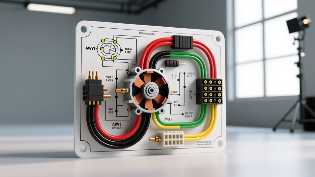
Introduction to Small Engine Magneto and Stator Systems
When diagnosing a no-spark or no-charge condition on a riding mower, commercial generator, or agricultural tractor, interpreting the small engine magneto wiring diagram is only the first step. Equally important is understanding the financial and practical requirements of the repair. Small engines, primarily manufactured by Briggs & Stratton, Kohler, and Honda, utilize a flywheel-driven magneto for ignition and a concealed stator for charging duties. Because these components operate in high-vibration, high-heat environments, wiring harness degradation, coil failure, and rectifier burnout are common failure modes.
This comprehensive analysis breaks down the exact diagnostic tools required, the OEM component costs, and the precise wiring specifications needed to troubleshoot and repair small engine electrical systems efficiently.
Essential Diagnostic Toolkit & Cost Analysis
Before tearing into the engine shroud, you must assemble the correct diagnostic equipment. Small engine electrical systems operate on a mix of high-voltage/low-amperage (ignition) and low-voltage/high-amperage (charging) circuits. Using improper tools can lead to misdiagnosis or damaged ECU components on newer EFI small engines.
- Digital Multimeter (DMM): A true-RMS multimeter is mandatory for accurately reading the high-frequency AC output of the stator. The Innova 3320 Auto-Ranging ($25) is sufficient for DIY, while professionals should use the Fluke 87V ($400) for its low-impedance (LoZ) mode, which eliminates ghost voltages on open kill circuits.
- Feeler Gauge Set (Brass/Steel): Required for setting the magneto air gap. Cost: $8 - $15. (Note: Use brass gauges when possible to avoid scratching the flywheel magnets).
- Harmonic Balancer / Flywheel Puller: Specific to the engine family (e.g., Kohler Command or Briggs Intek). Cost: $20 - $45.
- Wire Piercing Probes & Back-Probes: Essential for testing AMP Superseal connectors without damaging the weather-pack seals. Cost: $15.
- Soldering Station & Marine-Grade Heat Shrink: For repairing stator pigtails. Cost: $60.
Total DIY Toolkit Investment: $103 - $163 (excluding professional-grade Fluke meters).
Decoding the Small Engine Magneto Wiring Diagram
The typical small engine electrical schematic divides into two distinct sub-systems: the ignition magneto and the charging stator. While often housed under the same flywheel, their wiring diagrams and operational parameters are entirely separate.
Ignition Magneto Circuit
The ignition coil generates upwards of 25,000 volts to bridge the spark plug gap. The wiring for this circuit is remarkably simple but highly prone to grounding faults. The primary wire (kill wire) is typically Black or White (depending on OEM) and is usually 18 AWG. When the ignition key is turned to 'OFF', a mechanical switch grounds this wire to the engine block, collapsing the magnetic field and halting the spark.
Charging Stator & Rectifier Circuit
Engines equipped with a battery (e.g., electric-start riding mowers) feature a stator hidden beneath the flywheel. The stator outputs raw Alternating Current (AC), which must be converted to Direct Current (DC) via a rectifier/regulator. The wiring here requires heavier gauge wire due to the amperage load.
- Stator Output Wires: Typically Yellow or White, sized at 16 AWG or 14 AWG to handle 9 to 16 amps of continuous current without voltage drop.
- Rectifier DC Output: Typically Red, sized at 14 AWG, routed through an inline 20A or 30A fuse to the battery positive terminal.
- Rectifier Ground: Usually achieved via the mounting bracket to the engine block, though some OEMs use a dedicated Black ground wire.
Typical Briggs & Stratton / Kohler Stator Pinout Table
| Wire Color | AWG Size | Function | Destination / Pinout | Expected Voltage (3600 RPM) |
|---|---|---|---|---|
| Black | 18 AWG | Ignition Kill | Ignition Switch 'M' Terminal | 0V (Grounded to Stop) |
| Yellow / White (Pair) | 16 AWG | AC Stator Output | Rectifier/Regulator AC Pins | 28V - 35V AC |
| Red | 14 AWG | DC Charge Output | Battery Positive (+) via Fuse | 13.8V - 14.4V DC |
| Green / Bare | 16 AWG | Stator Ground | Engine Block / Chassis | N/A (Continuity to Ground) |
Financial Analysis: Component Repair vs. Replacement Costs
When a fault is isolated to the magneto or stator, technicians must weigh the cost of OEM replacement against aftermarket alternatives or complete engine swaps. According to Briggs & Stratton service documentation, attempting to rewind a small engine stator is rarely cost-effective due to the labor intensity of removing the flywheel and the low cost of replacement parts.
OEM vs. Aftermarket Pricing Matrix
| Component | OEM Cost (Approx.) | Aftermarket Cost | Labor Time (Flat Rate) |
|---|---|---|---|
| Ignition Coil (Magneto) | $35 - $55 | $18 - $25 | 0.5 Hours |
| Dual-Circuit Stator | $65 - $95 | $35 - $50 | 1.2 Hours |
| Voltage Regulator/Rectifier | $40 - $60 | $20 - $30 | 0.3 Hours |
| Complete Wiring Harness | $85 - $140 | N/A (OEM Only) | 2.0 Hours |
Note: Labor rates for small engine repair shops typically range from $85 to $125 per hour. A complete stator and rectifier replacement at a dealership will cost between $180 and $250, whereas the DIY parts cost is under $100.
Step-by-Step Diagnostic Workflow
Follow this structured workflow to validate the small engine magneto wiring diagram against real-world conditions. Always consult the specific Kohler or Briggs service manual for your exact engine family before proceeding.
Step 1: Verify the Kill Circuit Continuity
Disconnect the spark plug wire to prevent accidental starting. Unplug the engine harness connector. Set your DMM to Continuity/Ohms. Place one probe on the engine block (bare metal) and the other on the kill wire pin (usually Black). With the ignition key OFF, you should read near 0.0 Ohms. With the key ON, the meter should read 'OL' (Open Loop). If the circuit remains closed with the key ON, trace the wiring harness back to the ignition switch for a pinched wire or faulty switch.
Step 2: Test Stator AC Output (No-Load)
Disconnect the stator plug from the rectifier. Start the engine and run it at wide-open throttle (WOT), typically 3600 RPM for small engines. Set your DMM to AC Volts. Probe the two stator output wires (Yellow/White). You should read between 28V and 35V AC. If the voltage is below 20V AC, the flywheel magnets may be weakened, or the stator windings are internally shorted. Safety Warning: Never use a piercing probe on the stator wires, as moisture ingress will destroy the internal windings over time.
Step 3: Rectifier Diode Bridge Test
If the stator outputs correct AC voltage but the battery is not charging, the rectifier has likely failed. Remove the rectifier from the engine. Set the DMM to Diode Test mode. Test between the AC input pins and the DC output pin. You should read a forward voltage drop of 0.4V to 0.7V in one direction, and 'OL' when the probes are reversed. A reading of 0.0V indicates a shorted diode, requiring immediate rectifier replacement.
Step 4: Magneto Air Gap Adjustment
If the engine has no spark despite a good kill circuit, check the magneto air gap. Loosen the coil mounting bolts. Insert a 0.010-inch to 0.014-inch brass feeler gauge between the flywheel magnet and the coil legs. Rotate the flywheel to align the magnet with the coil. Tighten the mounting bolts to the OEM torque specification (typically 70-100 in-lbs) while holding the gauge in place. Remove the gauge; the magnetic force should hold the coil firmly against the gap specification. Refer to SAE technical standards regarding magnetic flux density and air gap tolerances for small internal combustion engines.
Conclusion
Mastering the small engine magneto wiring diagram is a highly cost-effective skill. By investing roughly $100 in a proper diagnostic toolkit and understanding the specific AWG requirements and voltage parameters of the stator and ignition circuits, DIY mechanics and fleet technicians can avoid unnecessary dealership labor charges. Always prioritize OEM connectors, use marine-grade heat shrink for any splices, and strictly adhere to the specified air gaps to ensure long-term reliability of the electrical system.