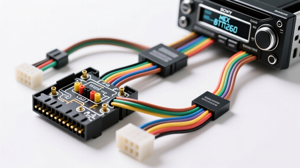
Introduction to the Sony MEX-BT2600 Electrical Architecture
Integrating an aftermarket single-DIN receiver requires a precise understanding of both the head unit's proprietary pinout and the vehicle's OEM electrical system. The Sony MEX-BT2600, a highly regarded Bluetooth-equipped CD receiver, features an internal 55W x 4 MOSFET amplifier and A2DP audio streaming. While searching for the official Sony MEX-BT2600 wiring diagram PDF is the first step for most installers, the factory documentation often lacks the real-world automotive integration data required for a flawless, noise-free installation.
Unlike modern Class-D digital amplifiers, the MEX-BT2600 relies on a traditional analog Class-AB MOSFET output stage. This architecture is highly sensitive to voltage drops, improper grounding, and impedance mismatches. According to the CTA Mobile Electronics Wiring Standards, maintaining strict adherence to EIA/CEA color codes and utilizing proper crimping techniques is critical to preventing thermal shutdown and alternator whine. This complete wiring walkthrough bridges the gap between the Sony schematic and your vehicle's dashboard harness.
Sony MEX-BT2600 Wiring Diagram PDF: Pinout & Color Code Matrix
The MEX-BT2600 utilizes Sony's proprietary 16-pin RC-236 harness connector. Below is the definitive translation of the Sony pinout mapped to the universal EIA/CEA aftermarket wire color standards. When adapting this unit to a vehicle-specific harness using a Crutchfield Vehicle Wiring Database reference, these are the exact wire functions you must match.
| Wire Color | Function | AWG | Circuit Notes & Specifications |
|---|---|---|---|
| Yellow | Battery (B+) | 18 AWG | Constant 12V. Protected by a 10A inline blade fuse. Powers memory and Bluetooth standby. |
| Red | Accessory (ACC) | 18 AWG | Switched 12V. Triggers unit power-on. Must read 0V when key is removed. |
| Black | Ground (GND) | 18 AWG | Chassis ground. Must be terminated to bare metal, never to a factory wiring loom. |
| Blue w/ White Stripe | System Remote Out | 18 AWG | +12V trigger for external amplifiers or powered antennas. Max current draw: 300mA. |
| Orange w/ White Stripe | Illumination | 18 AWG | Dimmer input. Accepts +12V to trigger night-mode display dimming. |
| White / White-Black | Front Left (+/-) | 18 AWG | 4-ohm minimum impedance. Do not ground the negative (Black-stripe) wires. |
| Gray / Gray-Black | Front Right (+/-) | 18 AWG | 4-ohm minimum impedance. Maintain phase alignment with Front Left. |
| Green / Green-Black | Rear Left (+/-) | 18 AWG | 4-ohm minimum impedance. Required for DSO (Digital Sound Organizer) processing. |
| Purple / Purple-Black | Rear Right (+/-) | 18 AWG | 4-ohm minimum impedance. Required for proper Bluetooth stereo imaging. |
Main Power, Ground, and Accessory Circuit Walkthrough
The most common point of failure in any MEX-BT2600 installation is the power and ground circuit. The unit ships with 18 AWG wire on the harness. While 18 AWG is sufficient for the unit's baseline 7A maximum current draw, upgrading the Yellow (Constant) and Black (Ground) wires to 16 AWG is highly recommended if you frequently listen at high volumes or experience voltage sag below 11.5V during heavy bass transients.
The Grounding Protocol
Never use 'T-tap' connectors or scotch-locks for the Black ground wire. These connectors pierce the wire insulation, exposing copper to moisture and causing high-resistance corrosion over time. Instead, utilize an adhesive-lined marine-grade heat shrink ring terminal. Locate a 10mm or 8mm structural chassis bolt behind the dashboard. You must use a wire brush or sandpaper to remove all paint, powder coating, and rust from the grounding surface. A poor ground will immediately manifest as a high-pitched alternator whine in your Bluetooth audio stream due to ground loop induction.
The European 'Memory Loss' Anomaly
If you are installing the MEX-BT2600 into certain European vehicles (specifically older Volkswagen, Audi, or Peugeot models), you may encounter a 'memory loss' issue where the unit forgets its EQ and Bluetooth pairing settings every time you turn off the car. This occurs because the OEM harness swaps the Constant 12V and Switched 12V pins at the radio connector. To resolve this, use a digital multimeter to test the vehicle's harness. If the pin that reads 12V with the key OFF is connected to your Sony's Red wire, simply swap the Red and Yellow wires at the aftermarket harness adapter.
Speaker Harness Integration and Phase Alignment
The Sony MEX-BT2600 is rated for 55W Peak x 4 channels, but its true RMS output is approximately 17W x 4 at 4 ohms. It is strictly a 4-ohm stable head unit. Wiring 2-ohm speakers or wiring dual voice coil subwoofers directly to the speaker outputs will cause the internal MOSFET IC to overheat and trigger the unit's thermal protection circuit, resulting in an abrupt 'PROTECT' error on the LCD display.
Furthermore, never ground the speaker negative wires (White-Black, Gray-Black, Green-Black, Purple-Black) to the vehicle chassis. Unlike older home audio equipment, the MEX-BT2600 uses a BTL (Bridge-Tied Load) amplifier configuration. Grounding a speaker negative wire will short the internal amplifier output directly to the chassis, instantly destroying the output IC. All speaker connections must remain floating and isolated.
Accessory, Illumination, and Remote Turn-On
The Blue/White wire provides a +12V, 300mA remote turn-on signal. If you are driving an external 5-channel amplifier for a subwoofer, this wire is perfectly suited to trigger the amp's remote terminal. However, if your amplifier requires more than 300mA to trigger its internal relays, you must use a standard 12V automotive relay to prevent frying the Sony's internal remote output transistor.
The Orange/White illumination wire is designed to accept a +12V signal when the vehicle's headlights are turned on, dimming the display to prevent night-blindness. In modern GM and Ford trucks utilizing PWM (Pulse Width Modulation) dimming circuits for the dashboard lights, connecting the Orange/White wire directly to the OEM dimmer circuit will cause the Sony display to flicker violently. If your vehicle uses PWM dimming, cap off the Orange/White wire and rely on the unit's manual dimmer button, or install a PWM-to-12V converter module.
Real-World Troubleshooting & Failure Modes
Parasitic Battery Draw
If your vehicle battery is dying overnight after installing the MEX-BT2600, the Bluetooth module may be failing to enter sleep mode. This is almost always caused by 'back-feeding' voltage through the Illumination (Orange/White) or Power Antenna wires. Disconnect the Orange/White wire and measure the current draw on the Yellow wire with the key off. It should read less than 5mA. If it reads higher, check for pinched wires behind the DIN sleeve that might be shorting to the metal dash frame.
Bluetooth Audio Dropouts and Static
While the MEX-BT2600 supports the SBC Bluetooth codec, RF interference from poorly routed USB charging cables or unshielded aftermarket LED lighting can cause audio dropouts. Ensure the Sony RC-236 harness is not bundled tightly alongside the vehicle's OBD-II data bus or high-current ignition wiring. Keeping a minimum 3-inch separation between the audio harness and high-current 12V wiring will eliminate induced electromagnetic interference (EMI) from your Bluetooth streams.