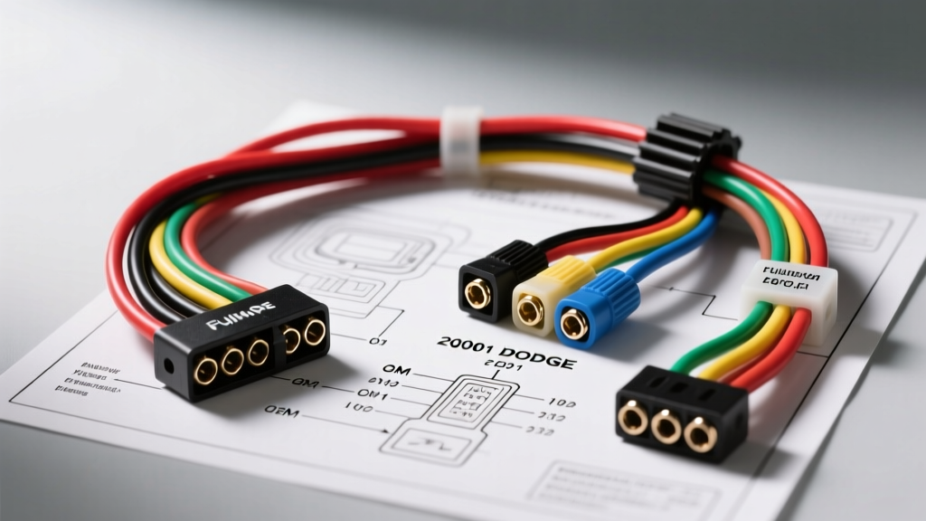
Understanding the 2001 Dodge Chrysler Audio Architecture
Upgrading the factory stereo in a 2001 Dodge Ram, Durango, Caravan, or Neon requires a solid understanding of the Chrysler audio architecture from that era. Unlike modern vehicles that rely on complex CAN-bus networks for basic radio power and data, the 2001 Dodge lineup utilizes a straightforward PCI (Programmable Communications Interface) bus and traditional hardwired 12V analog circuits. This makes the 2001 Dodge radio wiring diagram highly accessible for DIY enthusiasts and professional installers alike. However, the primary hurdle in these vehicles is not the head unit power wiring, but rather the factory Infinity premium audio system amplifier bypass and the specific Chrysler 7-pin and 5-pin connector configurations. In this comprehensive installation guide, we will break down the exact OEM wire color codes, AWG specifications, and step-by-step procedures to safely integrate a modern aftermarket double-DIN or single-DIN receiver without cutting a single factory wire.
Required Tools and Adapter Harnesses
Before dissecting the 2001 Dodge radio wiring diagram, you must gather the correct interface adapters and electrical tools. Attempting to hardwire directly to the vehicle's OEM harness is a violation of standard automotive electrical practices and will destroy the resale value of your truck or SUV.
- Wiring Harness Adapter: Metra 70-1858 or Scosche CR02B. These adapters plug directly into the factory Chrysler gray and black connectors and provide bare, color-coded wires that match standard aftermarket head unit wiring (EIA color code standard).
- Dash Kit: Metra 95-6500 (Double DIN) or 99-6500 (Single DIN) to adapt the 2001 Dodge bezel to the new receiver chassis.
- Wire Strippers: Precision strippers calibrated for 18 AWG to 12 AWG wire (e.g., Klein Tools 11055).
- Connection Method: Adhesive-lined marine-grade heat shrink and a high-wattage soldering iron. Avoid T-taps and twist connectors, which cause voltage drop and intermittent signal loss in high-vibration vehicle environments.
- Digital Multimeter: Required to verify constant and switched 12V sources before connecting the new head unit.
OEM 2001 Dodge Radio Wiring Diagram & Pinout Table
The 2001 Dodge factory radio typically connects via two main harnesses: a 7-pin gray connector (C1) handling power, ground, and front speakers, and a 5-pin or 7-pin black connector (C2) handling rear speakers and illumination. Below is the definitive pinout reference for the standard non-amplified and amplified Chrysler systems of this generation.
| Pin / Wire Color | Function | OEM AWG | Aftermarket Match |
|---|---|---|---|
| Pink / White Stripe | Constant 12V+ (Battery Memory) | 18 AWG | Yellow |
| Red / White Stripe | Switched 12V+ (Ignition Accessory) | 18 AWG | Red |
| Black / Light Green | Chassis Ground | 16 AWG | Black |
| Orange / Black Stripe | Dashboard Illumination | 20 AWG | Orange / White |
| Dark Green | Front Left Speaker (+) | 20 AWG | White |
| Dark Green / Black | Front Left Speaker (-) | 20 AWG | White / Black |
| Violet | Front Right Speaker (+) | 20 AWG | Gray |
| Violet / Black | Front Right Speaker (-) | 20 AWG | Gray / Black |
| Brown | Rear Left Speaker (+) | 20 AWG | Green |
| Brown / Black | Rear Left Speaker (-) | 20 AWG | Green / Black |
| Dark Blue | Rear Right Speaker (+) | 20 AWG | Purple |
| Dark Blue / Black | Rear Right Speaker (-) | 20 AWG | Purple / Black |
Note: If your 2001 Dodge is equipped with the factory Infinity amplifier, the speaker wires listed above will carry low-level pre-out signals rather than high-level amplified power. This requires a specific bypass procedure detailed in Phase 3.
Step-by-Step Head Unit Installation Guide
Phase 1: Dash Disassembly and Safety Protocols
Begin by disconnecting the negative terminal of the vehicle's battery. The 2001 Dodge Ram and Durango feature SRS (Supplemental Restraint System) airbag modules mounted in close proximity to the dashboard center stack; working with live 12V circuits poses a severe deployment risk. Allow the vehicle to sit for 10 minutes after battery disconnect to drain residual capacitor charge in the airbag module. Using a trim removal tool, carefully pry the bezel surrounding the radio and HVAC controls. The bezel is held in place by tension clips and two 7mm (or 5/16-inch) hex head screws located at the top corners. Once the screws are removed, the factory radio chassis slides out. Depress the locking tabs on the gray and black OEM connectors to release them from the rear of the factory unit.
Phase 2: Harness Splicing and AWG Considerations
Connect your Metra 70-1858 adapter harness to the vehicle's factory plugs. You will now splice the adapter's bare wires to your new aftermarket head unit's wiring harness. According to SAE J1128 standards for low-tension primary automotive cable, the OEM 18 AWG power wires are sufficient for standard 50W x 4 internal amplifiers. However, if your new receiver features a high-current internal amplifier or you are adding an external DSP, it is highly recommended to run a dedicated 12 AWG constant power wire directly to the battery with an inline 15A fuse, and upgrade the ground to a bare metal chassis point using a ring terminal. For standard installations, strip 1/4 inch of insulation from both the adapter and head unit wires, twist them tightly, apply rosin-core solder, and seal with 3/16-inch adhesive-lined heat shrink. This prevents copper oxidation and ensures a vibration-proof connection that will last the lifespan of the vehicle.
Phase 3: Bypassing the Factory Infinity Amplifier
The most common point of failure when referencing a 2001 Dodge radio wiring diagram is the Infinity premium audio system. If your truck has the Infinity badge on the dash, the factory head unit outputs low-level (pre-amp) signals to a multi-channel amplifier located under the passenger seat or behind the rear cab wall. If you plug a standard aftermarket harness directly into this system, you will get zero sound, and the low-level signals may trigger the new head unit's short-circuit protection mode.
The Bypass Procedure:
- Locate the factory Infinity amplifier and disconnect its main power and speaker output harnesses.
- Identify the high-level speaker wires exiting the amplifier and heading toward the door pillars. These wires are typically color-coded identically to the standard radio harness (Dark Green, Violet, Brown, Dark Blue with corresponding black tracers).
- Run new 18 AWG speaker wire from your aftermarket head unit's harness directly to these high-level speaker wires, completely bypassing the dead factory amplifier.
- Alternatively, use a specialized amplifier retention harness (like the Axxess XLOC-CHY) which provides RCA pre-outs to plug into your aftermarket receiver, allowing you to retain the factory amplifier if it is still in good working condition.
Multimeter Testing and Pre-Assembly Verification
Before pushing the new head unit into the dash kit, reconnect the vehicle's battery and power on the system. Using a digital multimeter set to DC Voltage, probe the Yellow wire at the back of the head unit; it should read 12.2V to 12.6V regardless of the key position. Probe the Red wire; it should read 0V with the key off, and 11.5V to 12.4V when the key is in the 'ACC' or 'RUN' position. Test the ground wire for continuity to the chassis (should read near 0.00 ohms). Finally, use the balance and fader controls on the new receiver to verify that all four speakers are producing high-level audio and that the left/right and front/rear orientations match the physical speaker locations.
Troubleshooting Common Installation Gremlins
- Symptom: Radio turns on, but resets to 12:00 and loses presets every time the truck is turned off.
Cause: The Constant 12V (Pink/White) and Switched 12V (Red/White) wires are reversed. The head unit is losing its memory circuit power when the ignition cuts off. Swap the Yellow and Red wires at the harness adapter. - Symptom: Head unit powers on, but shuts off immediately when the volume is increased past level 15.
Cause: A speaker wire is shorting against the metal radio chassis or dash bracing. Inspect your speaker wire splices and ensure no bare copper is exposed. Use electrical tape or heat shrink to isolate the connections. - Symptom: Dash illumination does not match the rest of the truck's interior lights at night.
Cause: The Orange/Black illumination wire on the Chrysler harness operates on a multiplexed dimmer circuit. If your aftermarket radio has a standard 'Illumination' wire (Orange) and a 'Dimmer' wire (Orange/White), connect the Chrysler Orange/Black wire ONLY to the radio's standard Illumination wire. Connecting it to the dimmer wire can cause back-feeding and blow the vehicle's interior lighting fuse.
Authoritative Wiring References
For further technical validation, installers should consult the official Haynes Repair Manuals for Chrysler Trucks and SUVs, which provide chassis-specific grounding point locations and fuse box diagrams. Additionally, verifying adapter pinouts against Metra Electronics' official application guide ensures compatibility across different 2001 Dodge trim levels, including the Ram 1500, 2500, and 3500 series. Always prioritize soldered connections and adhere to SAE automotive wiring standards to guarantee a safe, reliable, and high-fidelity audio upgrade.