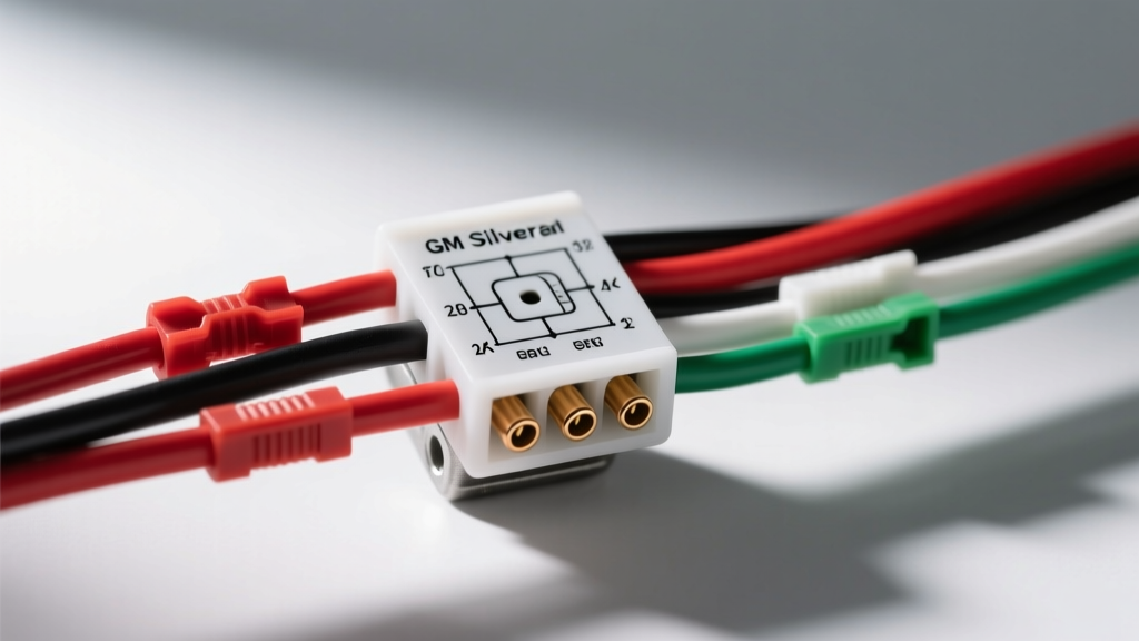
Understanding the GM 4-Pin Fuel Sender Unit Wiring Diagram
When performing a fuel pump module replacement or an engine swap involving a GM truck platform, interpreting the fuel sender unit wiring diagram is critical for accurate fuel level telemetry and proper pump operation. The GM 4-pin fuel tank module harness integrates both the high-current fuel pump circuit and the low-voltage fuel level sender circuit into a single flange connector. Miswiring this harness will result in blown PCM fuses, erratic fuel gauge behavior, or complete pump failure.
This practical installation guide focuses on the widely used GM 4-pin Metri-Pack configuration found in GMT800 and GMT900 platforms. Unlike older 3-wire setups, the 4-pin system isolates the high-current pump ground from the sensitive sender ground, preventing voltage offset errors that cause the fuel gauge to read inaccurately when the pump is under heavy load.
Pinout Configuration and Wire Color Codes
Before cutting, crimping, or soldering any wires, you must verify the cavity assignments. GM utilizes the Aptiv Metri-Pack Connector Series for this flange, specifically mixing 150-series cavities for low-current signals and 280-series cavities for high-current pump feeds. Below is the definitive pinout reference for the standard 4-pin fuel sender and pump module.
| Pin / Cavity | Function | OEM Wire Color | AWG Size | Terminal Series |
|---|---|---|---|---|
| Pin A | Fuel Level Signal (to PCM/BCM) | Purple | 18 AWG | Metri-Pack 150 |
| Pin B | Fuel Level Sender Ground | Black | 18 AWG | Metri-Pack 150 |
| Pin C | Fuel Pump 12V Feed | Grey | 12 AWG | Metri-Pack 280 |
| Pin D | Fuel Pump High-Current Ground | Black w/ White Stripe | 12 AWG | Metri-Pack 280 |
Technical Note on Resistance: The fuel level sender operates on a variable resistor (potentiometer) principle. For this specific GM generation, the resistance sweep is 40 Ohms (Empty) to 250 Ohms (Full). The PCM provides a 5V reference to Pin A. As the float arm moves, the resistance changes, altering the voltage return signal. An empty tank yields approximately 0.7V, while a full tank yields roughly 4.2V.
Pre-Installation Diagnostics: Testing the Sender Circuit
Never install a new sender unit into the tank without first verifying the integrity of the chassis-side wiring harness. A short to ground on the Purple signal wire will cause the PCM to interpret the tank as completely empty, while a short to voltage will peg the gauge at full.
Step 1: Verify PCM 5V Reference Voltage
- Turn the ignition to the 'ON' position (engine off).
- Set your digital multimeter (DMM) to DC Volts.
- Probe the chassis-side harness Pin A (Purple) and Pin B (Black).
- You should read a stable 4.8V to 5.1V. If you read 0V, check the PCM 5V reference fuse and inspect the Purple wire for a dead short to chassis ground.
- If you read 12V, the wire is shorted to a battery-positive source, which will instantly destroy the PCM's internal analog-to-digital (A/D) converter.
Step 2: Bench Test the Sender Resistance
Before dropping the module into the tank, validate the mechanical sweep of the new sender unit. Connect your DMM to the sender-side pins (A and B) using the Ohms (Ω) setting. Manually move the float arm from the bottom stop to the top stop. The resistance must sweep smoothly from 40Ω to 250Ω without any infinite spikes or 'dead spots'. A dead spot indicates a worn carbon track on the resistor board, which will cause the fuel gauge to flutter while driving over bumps.
Step-by-Step Installation & Wiring Guide
Proper termination and routing are just as important as the wiring diagram itself. The environment beneath a vehicle is hostile, characterized by moisture, road salt, and extreme temperature cycling. All underbody wiring must comply with the SAE J1128 Low Tension Primary Cable Standard for thermal and chemical resistance.
Step 3: Prepping the Harness and Terminals
Do not use standard vinyl electrical tape or generic butt connectors for the fuel sender harness. The capillary action of stranded wire will wick moisture directly into the crimp barrel, leading to galvanic corrosion and high-resistance voltage drops.
- Stripping: Use a precision wire stripper to remove exactly 5mm of insulation from the 18 AWG signal wires and 7mm from the 12 AWG pump wires. Do not nick the copper strands; nicked strands reduce the cross-sectional area and create hot spots under the 10-amp continuous draw of the fuel pump.
- Crimping: Use a ratcheting crimp tool specifically calibrated for Metri-Pack terminals. The crimp must feature an 'F-crimp' geometry on the wire barrel and a firm insulation grip on the rear tabs. A loose crimp on Pin C (Pump Feed) will cause voltage drop, starving the pump and leading to premature commutator failure.
- Sealing: Slide dual-wall adhesive-lined heat shrink over every splice. The inner meltable adhesive layer creates a watertight environmental seal, preventing sulfation of the copper strands.
Step 4: Routing and Securing the Harness
Route the fuel sender harness along the factory frame rail clips, maintaining a minimum clearance of 6 inches from the exhaust system. If the factory convoluted loom is brittle or cracked, replace it with split-loom tubing rated for 125°C. Secure the harness every 12 inches using UV-resistant nylon zip ties or factory-style push-clips. Ensure the drip loop is maintained before the harness enters the cab or connects to the main chassis bulkhead, preventing water from tracking directly into the connector cavity.
Common Failure Modes and Troubleshooting Decision Tree
Even with a perfect installation, electrical gremlins can occur. Use this diagnostic decision tree, adapted from standard Haynes Automotive Electrical Manuals, to isolate faults in the fuel sender circuit.
| Symptom | Probable Cause | Diagnostic Action & Fix |
|---|---|---|
| Gauge reads 'Empty' and DIC shows 'Service Fuel Level Sensor' | Open circuit on Pin A (Purple) or Pin B (Black). | Check for 5V reference at the harness. If 5V is present, check continuity to PCM. Repair broken Purple wire. |
| Gauge pegs 'Full' and never drops | Short to ground on Pin A (Purple) or internal sender short. | Disconnect PCM and sender. Check resistance between Pin A and chassis ground. If near 0 Ohms, repair shorted wire. |
| Gauge fluctuates wildly while driving | Worn sender resistor card or loose Metri-Pack terminal. | Perform the bench sweep test. If resistance jumps, replace sender. If smooth, check terminal tension on Pin A/B. |
| Fuel pump runs, but whines loudly and starves at high RPM | Voltage drop on Pin C (Grey) or Pin D (Black/White). | Perform a loaded voltage drop test across the pump circuit. Total drop must be less than 0.2V. Replace corroded pins. |
Advanced Tip: Addressing Ground Offset Errors
If your fuel gauge reads accurately when the truck is idling but drops by 1/8th of a tank when accelerating or when the fuel pump is under heavy load, you are experiencing a ground offset error. This happens when the sender ground (Pin B) and the pump ground (Pin D) share a corroded chassis ground point. The high current from the fuel pump creates a voltage differential across the poor ground, which the PCM interprets as a change in sender resistance. Always ensure Pin B is grounded to a dedicated, clean, bare-metal PCM sensor ground node, completely isolated from the high-current fuel pump ground star-point.