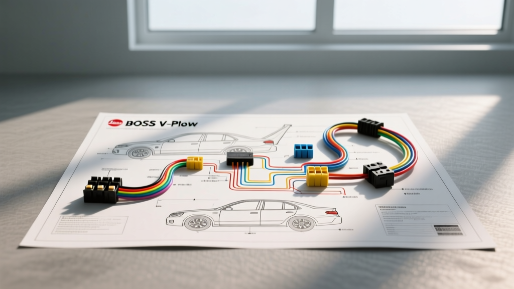
Introduction to BOSS V-Plow Multiplex Architecture
Troubleshooting the electrical system of a BOSS V-Plow requires more than just a basic test light. Modern BOSS V-Plows (including the V-XT and standard V-Plow lines) utilize a sophisticated Multiplex electrical architecture. Unlike older relay-based systems that send raw 12V power directly to hydraulic solenoids, the Multiplex system uses a central control module and a 13-pin connector to send low-current data signals and switched power. When a plow fails to lift, angle, or communicate with the in-cab controller, blindly swapping parts can lead to catastrophic failure of the SmartHitch 2 or Multiplex control nodes. This step-by-step troubleshooting flow leverages the wiring diagram for BOSS V-Plow systems to isolate faults logically, from the high-amperage main power feeds down to the individual hydraulic valve coils.
Required Diagnostic Tools & Safety Protocols
Before probing any wires, ensure the vehicle is parked on level ground, the parking brake is engaged, and the hydraulic system is fully depressurized. Never work under an unsupported plow blade.
- Digital Multimeter (DMM): Required for measuring voltage drop, resistance (Ohms), and data line continuity. An automotive-specific DMM with a duty-cycle and frequency setting is highly recommended.
- 12V Test Light: Use only on high-amperage power circuits (e.g., main solenoid feed). Never use a standard incandescent test light on Multiplex data pins, as the current draw can fry the control module's internal logic board.
- Dielectric Grease: Nyogel 760G or equivalent. Standard silicone grease is insufficient for the high-vibration, high-moisture environment of snowplow connectors.
- Wire Piercing Probes: Avoid back-probing the 13-pin connector with paperclips or standard probes, which will spread the female terminals and cause future intermittent connection failures.
Phase 1: Main High-Amperage Power Circuit Verification
The most common cause of a 'dead' BOSS V-Plow is a failure in the main power delivery system. The plow motor requires massive current (often exceeding 150 Amps under heavy load), meaning even minor corrosion will cause severe voltage drop.
- Inspect the 150A Mega Fuse: Located on the vehicle-side battery harness. Use your DMM to check for continuity. A blown Mega Fuse usually indicates a seized hydraulic pump motor or a shorted main solenoid.
- Verify Main Solenoid Activation: Have an assistant toggle the controller to the 'Lift' position. Listen for a heavy, metallic 'clack' from the under-hood solenoid. If silent, check the 15A Mini fuse on the red/white ignition-switched wire that triggers the solenoid coil.
- Perform a Voltage Drop Test: Set your DMM to DC Volts. Place the red probe on the battery positive post and the black probe on the plow motor's positive terminal (while the system is actively trying to lift). A reading above 0.5V indicates excessive resistance in the 2 AWG battery cable or crimp lugs. According to SAE J1128 standards for low-tension primary cables, heavy-duty circuits must maintain minimal voltage drop to prevent thermal runaway.
- Check Ground Integrity: The plow ground cable must be bolted to bare, unpainted metal on the vehicle chassis. Torque the ground ring terminal to 15 lb-ft. Sand away any rust or undercoating before reattaching.
Phase 2: 13-Pin Multiplex Connector & Data Line Integrity
If the main motor engages but individual V-Plow functions (like scooping or wing angling) fail, the fault lies in the Multiplex harness. The 13-pin connector carries both power and serial data between the cab controller and the plow-mounted control module.
Disconnect the 13-pin connector and inspect for green copper oxide corrosion. Clean with electrical contact cleaner and pack the female side with Nyogel 760G before reconnecting. Use the reference table below to test specific pins.
Reference Table: BOSS 13-Pin Multiplex Pinout & Wire Specs
| Pin | Wire Color | AWG | Function / Circuit Description | Diagnostic Target Value |
|---|---|---|---|---|
| 1 | Red | 10 | 12V+ Constant Battery Feed (Module Power) | 12.2V - 12.6V (Key Off) |
| 2 | Black | 10 | Main Module Ground | < 0.1 Ohms to Chassis |
| 3 | White | 16 | Multiplex Data Line A (CAN High / Serial) | Continuity to Cab Controller |
| 4 | Green | 16 | Multiplex Data Line B (CAN Low / Serial) | Continuity to Cab Controller |
| 5 | Orange | 14 | Ignition Switched 12V+ (Wake-Up Signal) | 12V+ (Key On) |
| 6 | Brown | 14 | Plow Lighting Common Ground | < 0.2 Ohms to Chassis |
| 7 | Yellow | 14 | Right Turn / Hazard Signal Feed | Pulsing 12V (Hazard On) |
| 8 | Blue | 14 | Left Turn / Hazard Signal Feed | Pulsing 12V (Hazard On) |
Note: Pin configurations can vary slightly based on the exact model year and whether the system utilizes the SmartHitch 2 or newer Multiplex nodes. Always cross-reference with the BOSS Snowplow Official Service Manuals for your specific serial number.
Phase 3: Hydraulic Valve Solenoid Resistance Testing
The BOSS V-Plow relies on a complex manifold of hydraulic valves (typically B, C, D, E, F, G, and H valves) to achieve V-Plow, Scoop, and independent wing movements. If the controller displays a specific valve error code, or if a function is entirely dead while others work, test the solenoid coil.
- Disconnect the 2-pin weather-pack connector at the suspect solenoid (e.g., the 'D' valve for left angling).
- Set your DMM to Ohms (Ω).
- Place the probes across the two terminals of the solenoid coil (not the harness side).
- Specification: A healthy BOSS hydraulic solenoid coil should read between 8.0 and 12.0 Ohms at room temperature.
- Failure Modes: A reading of 0.0 - 3.0 Ohms indicates an internal short. If you reconnect a shorted coil, it will instantly draw excessive amperage and burn out the internal driver transistor on the Multiplex control module. A reading of OL (Open Loop) indicates a broken internal winding, requiring solenoid replacement.
Symptom-Cause-Fix Decision Tree
Use this rapid diagnostic tree to isolate the root cause of common BOSS V-Plow electrical failures.
Symptom A: In-Cab Controller Powers On, But Plow Does Not Move At All
- Step 1: Check 150A Mega Fuse. (Blown? Replace fuse and test motor for dead short).
- Step 2: Listen for main solenoid click. (No click? Check 15A mini fuse and ignition-switched Orange wire on Pin 5).
- Step 3: Solenoid clicks, but motor doesn't spin. (Perform voltage drop test on 2 AWG motor cables. If cables are good, the motor brushes are likely worn or the pump is mechanically seized).
Symptom B: Controller Displays 'No Plow Detected' or Communication Error
- Step 1: Inspect 13-Pin connector for bent pins or moisture ingress.
- Step 2: Test Data Lines (Pins 3 & 4) for continuity from the plow module to the cab controller. (Open circuit? Repair broken 16 AWG wire in the flex conduit near the grille).
- Step 3: Verify Pin 1 (Red) has constant 12V and Pin 2 (Black) has a clean ground at the plow module. (Loss of power resets the Multiplex node, breaking data handshake).
Symptom C: Right Wing Angles, But Left Wing Fails
- Step 1: Swap the left and right solenoid connectors at the harness. If the left wing now works and the right fails, the issue is the solenoid coil, not the wiring.
- Step 2: If the left wing still fails with the known-good connector, check the specific output pin on the Multiplex module for a burned driver circuit.
- Step 3: Check for a mechanical crossover relief valve failure in the hydraulic manifold (if electrical tests pass, the fault is hydraulic, not electrical).
Preventative Maintenance & Best Practices
To prevent the majority of wiring faults outlined above, implement an end-of-season maintenance routine. Disconnect all harnesses, clean with CRC QD Contact Cleaner, and apply a liberal coat of Nyogel 760G. Inspect the 14 AWG and 16 AWG lighting and data wires where they pass through the vehicle's front grille or bumper, as these are highly susceptible to chafing from road debris and vibration. Protect any repaired wires using adhesive-lined heat shrink tubing to maintain the IP67 waterproof rating of the automotive wiring harness. By systematically following this wiring diagram troubleshooting flow, you can accurately diagnose BOSS V-Plow faults without resorting to guesswork or unnecessary parts replacement.