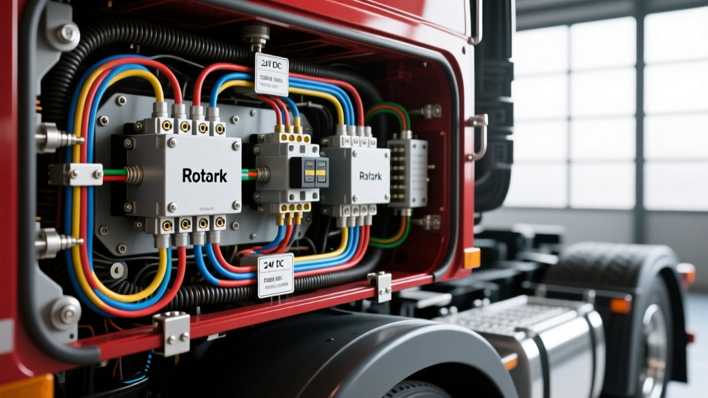
Upgrading Heavy-Duty Fluid Management with the Rotork 200-000
When executing complex expedition truck builds, custom motorhome fabrications, or heavy-duty commercial fluid management modifications, standard automotive 12V actuators often fall short. They lack the torque, IP68 environmental sealing, and duty cycle reliability required for critical systems like diesel coolant bypasses, motorized fuel transfer valves, or heavy-duty air suspension dump systems. This is where integrating an industrial-grade actuator becomes necessary. Specifically, the Rotork IQ series, adapted for heavy vehicle applications, provides exceptional reliability. However, adapting industrial equipment to a mobile 24V DC or 12V DC chassis environment requires a deep understanding of the specific rotork wiring diagram 200 000 series schematics, proper AWG sizing, and robust signal isolation.
This comprehensive modification guide details the exact electrical integration process for mounting and wiring a Rotork 200-000 series motorized valve actuator to a heavy-duty truck chassis. We will cover power supply calculations, control circuit pinouts, relay logic, and telematics feedback integration, ensuring your upgrade meets strict automotive electrical standards.
System Architecture and Power Supply Requirements
Unlike standard industrial applications that rely on 3-phase AC power, automotive and heavy-truck modifications require adapting the actuator to the vehicle's native 24V DC electrical system (common in Class 8 trucks like Freightliner Cascadias or heavy expedition vehicles like the Unimog U500). The Rotork 200-000 variant configured for DC applications utilizes an internal DC motor with a specialized control board that handles the reversing logic internally.
Because electric motors draw significant inrush current during startup and under high-torque loads (such as breaking the seal on a high-pressure ball valve), your wiring must be sized to handle peak amperage without excessive voltage drop. According to the SAE J1128 Low Tension Primary Cable Standard, wire gauge selection must account for both continuous current and ambient engine bay temperatures, which frequently exceed 85°C (185°F).
AWG Sizing and Voltage Drop Calculations
For a standard 24V DC Rotork actuator drawing a continuous 8A with a peak inrush of 18A, you must minimize resistance. Using standard TXL (cross-linked polyethylene) automotive wire, follow these specifications for a 15-foot run from the battery distribution block to the actuator:
- Motor Power (+24V DC): 10 AWG TXL Red wire. Rated for 30A in high-temperature zones. Protect with a 20A Maxi circuit breaker or slow-blow fuse to accommodate inrush current without nuisance tripping.
- Motor Ground: 10 AWG TXL Black wire. Must be terminated directly to the vehicle's main chassis ground stud or a dedicated heavy-duty ground bus bar. Do not rely on sheet metal grounding for high-amperage inductive loads.
- Control Signals: 18 AWG TXL. Used for Open/Close commands and feedback signals. These carry minimal current but require shielding if routed near high-amperage alternator cables or ignition coil wires to prevent electromagnetic interference (EMI).
Control Circuit Pinout and Deutsch Connector Integration
To maintain the IP68 waterproof rating of the Rotork actuator in harsh under-chassis environments, never hard-wire the harness directly into the actuator's terminal block. Instead, use a Deutsch DT06-6S plug mated to a DT04-6P receptacle. This allows for quick disconnects during maintenance or chassis articulation events. Below is the precise pinout configuration derived from the Rotork IQ Installation and Configuration Manual, adapted for the 200-000 DC mobile variant.
| Deutsch Pin | Actuator Terminal | Wire Color (SAE) | AWG | Function / Signal Type |
|---|---|---|---|---|
| 1 | L1 (+) | Red | 10 | Main Power Supply (24V DC) |
| 2 | L2 (-) | Black | 10 | Main Ground (Chassis) |
| 3 | Cmd Open | Yellow | 18 | Open Command (Switch to +24V) |
| 4 | Cmd Close | Blue | 18 | Close Command (Switch to +24V) |
| 5 | Sig Com | White | 18 | Feedback Signal Common (Ground) |
| 6 | Sig Out | Green | 18 | Position Feedback (4-20mA) |
Note: When crimping Deutsch contacts, always use the proper DT series wedgelocks and apply a small amount of dielectric grease to the O-rings before mating to prevent moisture ingress and subsequent galvanic corrosion.
Switchgear and Relay Logic for Cab Control
While the Rotork 200-000 internal board handles the heavy DC contactor switching, the control signals (Pins 3 and 4) must be triggered cleanly. Running 18 AWG control wires directly from a dashboard toggle switch to the actuator is acceptable for short distances, but for a heavy truck where the cab might tilt or the run exceeds 10 feet, utilizing Bosch-style ISO mini relays is best practice.
Use a heavy-duty DPDT (Double Pole, Double Throw) center-off momentary toggle switch in the cab. Wire the switch to trigger two 30A SPDT relays mounted in a sealed fuse/relay box near the actuator. This ensures that the 18 AWG signal wires only carry the minimal coil current (approx. 150mA), eliminating voltage drop across the chassis and ensuring the Rotork logic board receives a crisp, clean 24V trigger signal. Always install flyback diodes (e.g., 1N4007) across the relay coils to suppress inductive voltage spikes that could back-feed and damage the truck's sensitive CAN-bus modules or body controller.
Telematics and 4-20mA Feedback Loop Integration
One of the primary reasons for choosing the Rotork 200-000 for a high-end vehicle modification is the precise position feedback. The actuator outputs a 4-20mA analog signal corresponding to the valve's exact rotational position (0 to 90 degrees). In a mobile application, you typically want to read this data via a custom CAN-bus node, an Arduino-based dashboard display, or a commercial telematics GPS tracker.
Most automotive microcontrollers and telematics ADC (Analog-to-Digital Converter) inputs read voltage (0-5V or 0-12V), not current. To convert the 4-20mA signal to a readable 1-5V signal, you must wire a precision 250-ohm, 1% tolerance shunt resistor in parallel across the Signal Common (Pin 5) and Signal Out (Pin 6).
- 4mA (Valve Closed): 4mA x 250Ω = 1.0V
- 12mA (Valve 50%): 12mA x 250Ω = 3.0V
- 20mA (Valve Open): 20mA x 250Ω = 5.0V
Route this 1-5V signal through a shielded twisted-pair cable to your controller's ADC pin, grounding the shield at the controller end only to prevent ground loops.
Troubleshooting Common Actuator Faults
Integrating industrial hardware into a vibrating, high-EMI automotive environment introduces unique failure modes. Use the following diagnostic decision tree when troubleshooting your Rotork modification:
Symptom: Actuator Hums but Fails to Rotate
- Cause 1: Severe voltage drop under load. The internal logic board detects low voltage and aborts the stroke to protect the motor.
- Fix: Measure voltage directly at the Deutsch plug Pins 1 and 2 while the switch is engaged. If voltage drops below 20V DC, upgrade the power/ground wires from 10 AWG to 8 AWG, or check for corrosion at the chassis ground lug.
- Cause 2: Mechanical binding in the valve linkage. The Rotork's internal thermal overload switch has tripped.
- Fix: Allow 15 minutes for the bimetallic thermal switch to reset. Inspect the valve stem for debris or misalignment. Apply anti-seize to the mechanical coupling.
Symptom: Telematics Reads Erratic Position Data
- Cause 1: EMI interference on the 4-20mA feedback loop from the alternator or ignition system.
- Fix: Ensure the feedback wires (Pins 5 and 6) are routed at least 6 inches away from high-current AC or pulsing DC cables. Verify the shield drain wire is grounded at a single point.
- Cause 2: Failing shunt resistor or poor crimp connection on the signal common.
- Fix: Test the 250-ohm resistor with a multimeter. Replace if tolerance has drifted. Re-crimp the Deutsch pins using a proper ratcheting crimper to ensure a gas-tight connection.
By strictly adhering to these wiring protocols, AWG sizing standards, and signal isolation techniques, your Rotork 200-000 valve actuator upgrade will deliver years of reliable, heavy-duty service in the most demanding mobile environments.