The True Cost of Schematic Diagram Wiring Diagnostics
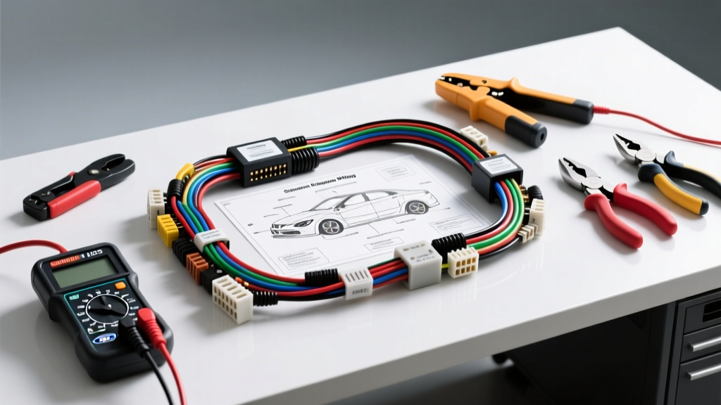
Interpreting a factory schematic diagram wiring layout is only half the battle in modern automotive electrical repair. Once you have identified the circuit path, pin configuration, and wire color codes, you must physically interact with the vehicle's harness without causing secondary damage. For professional technicians and serious DIYers, transitioning from reading a schematic to executing a flawless repair requires a specialized arsenal of diagnostic and terminal service tools. This analysis breaks down the exact financial investment and hardware requirements necessary to properly trace, test, and repair circuits based on complex schematic diagram wiring references.
Tier 1: Essential Electrical Testing Hardware
When you rely on a schematic diagram wiring reference to trace a 5-volt reference circuit or a high-speed CAN-bus fault, standard test lights are obsolete and dangerous. You need precision instruments that respect the delicate solid-state logic of modern Engine Control Modules (ECMs) and Body Control Modules (BCMs).
Digital Multimeters (DMM) & Oscilloscopes
A true-RMS Digital Multimeter with at least 10 Megohms of impedance is non-negotiable. The industry standard, the Fluke 87V (approximately $420), provides the reliability needed to measure millivolt drops across a ground circuit. However, when a schematic diagram wiring guide indicates a variable reluctance sensor or a high-speed communication bus (like GM GMLAN or Ford HS-CAN), a DMM is too slow. You must invest in an automotive oscilloscope, such as the PicoScope 4425A ($650+), to visualize the actual square wave or CAN-bus differential voltage in real-time.
Back-Probes and Breakout Boxes
Piercing wire insulation with a T-pin to test a circuit is a cardinal sin in automotive electrical repair; it introduces moisture and guarantees future corrosion. Instead, technicians must use ultra-fine back-probes. For standard 20 AWG (0.5mm²) sensor wires, flexible needle probes cost around $25 for a set. For smaller 22 AWG (0.35mm²) CAN-bus wires, specialized micro-probes are required. Furthermore, OEM-specific ECU breakout boxes ($150–$300 per manufacturer) allow you to test every pin at the module connector simultaneously while referencing your schematic diagram wiring layout, eliminating the risk of terminal spread.
Tier 2: Terminal Service & Crimping Investments
The most overlooked cost in electrical diagnostics is terminal service. Modern vehicles utilize sealed, micro-miniature connectors from manufacturers like TE Connectivity and Yazaki. Replacing a single corroded pin requires exact-match terminals, silicone weather seals, and precision crimping dies.
Terminal Extraction and Insertion
Plastic connectors feature primary and secondary locking mechanisms (TPA/CPA). Removing a terminal without breaking the micro-plastic locking tang requires specialized extraction tubes and picks. A comprehensive master extraction kit (such as those from HCT Tools or Lisle) costs between $150 and $250. These kits include double-sided hollow tubes designed to depress the locking barbs on TE Automotive 1.2mm and 0.64mm series terminals without damaging the housing.
Precision Crimping and Wire Splicing
Twisting wires together and taping them is unacceptable for modern sensor circuits. According to SAE J1939 CAN-Bus Standards, communication bus splices must maintain specific impedance and twist rates. To achieve this, you need a ratcheting micro-crimper ($120–$200) with interchangeable dies for open-barrel terminals. For splicing, ultrasonic welders are the OEM standard, but high-quality solder-seal heat shrink (e.g., Raychem) and ratcheting crimpers for butt connectors are the accepted aftermarket alternatives, costing roughly $40 for a premium kit.
Tier 3: Information Systems & Schematic Access
You cannot diagnose a circuit without the map. Accessing accurate, factory-level schematic diagram wiring databases is a recurring operational cost. While free forums exist, they often feature incomplete or incorrect pinouts that lead to misdiagnosed modules.
- OEM Service Portals: Subscriptions to GM TDS, Ford FMCDealer, or Stellantis TechConnect range from $40 for a 3-day pass to $1,500+ annually. These provide the most accurate schematic diagram wiring layouts, including exact connector cavity views and ground distribution charts.
- Aftermarket Databases: Platforms like Mitchell 1 ProDemand or Identifix cost roughly $300–$500 per month. They redraw OEM schematics into standardized formats, which speeds up tracing but occasionally obscures OEM-specific connector cavity numbering.
Case Study: Tracing a GM GMLAN Fault via Schematic Diagram Wiring
To illustrate how these tools and costs converge, consider diagnosing a U0100 (Lost Communication with ECM) code on a late-model GM vehicle. The schematic diagram wiring reference points to the High-Speed GMLAN bus.
Circuit Specifications & Pinout Data
According to the schematic, the ECM communicates via Connector X2 (Black). The relevant pins are:
- Pin 14 (CAN-H): Dark Green with White tracer, 0.5mm² (20 AWG)
- Pin 15 (CAN-L): Dark Green with Black tracer, 0.5mm² (20 AWG)
The schematic diagram wiring layout also indicates a 120-ohm termination resistor located inside the ECM and another inside the BCM. To diagnose a total bus shutdown, the technician must use the Fluke 87V to measure resistance across Pins 14 and 15 at the Data Link Connector (DLC) with the battery disconnected. A reading of 60 ohms indicates both termination resistors are present in parallel. A reading of 120 ohms means one module is disconnected or a wire is broken. A reading of near 0 ohms indicates the CAN-H and CAN-L wires are shorted together.
Executing the Repair
If the fault is isolated to a corroded Pin 14 at the ECM X2 connector, the technician uses the TE Connectivity 1.2mm extraction tool to remove the damaged terminal. They then strip 5mm of a new 20 AWG Dark Green/White wire, crimps a new Yazaki 09628-3 equivalent terminal using the open-barrel ratcheting crimper, inserts the silicone secondary seal, and seats it into the connector until the locking tang clicks. This precise workflow, dictated entirely by the schematic diagram wiring data, ensures the CAN-bus impedance remains stable and the module communicates reliably.
Comprehensive Tool & Cost Matrix
Below is a structured breakdown of the financial investment required to build a professional-grade electrical diagnostic bench capable of executing repairs derived from schematic diagram wiring analysis.
| Tool Category | Specific Example | Est. Cost | Application in Schematic Diagram Wiring |
|---|---|---|---|
| Digital Multimeter | Fluke 87V True-RMS | $420 | Voltage drop testing, verifying 5V refs, checking termination resistance. |
| Oscilloscope | PicoScope 4425A | $650 | Visualizing CAN-bus differential voltages and PWM actuator signals. |
| Terminal Extraction | HCT Tools Master Kit | $180 | Safe removal of micro-terminals without breaking connector housings. |
| Precision Crimper | Ideal or TE Ratcheting Crimper | $150 | Creating OEM-spec open-barrel crimps for 0.35mm² to 2.0mm² wires. |
| ECU Breakout Box | OEM-Specific Harness Kit | $250 | Simultaneous pin testing while referencing schematic cavity views. |
| Information System | Mitchell 1 ProDemand | $400/mo | Access to standardized schematic diagram wiring and ground charts. |
Conclusion: The ROI of Proper Tooling
While the initial capital expenditure for a professional electrical diagnostic setup can easily exceed $2,500 when factoring in high-end scan tools, oscilloscopes, and database subscriptions, the return on investment is undeniable. Misdiagnosing a $1,200 ECM because of a $5 broken wire or a poor solder joint is a costly mistake. By investing in the correct extraction tools, precision crimpers, and reliable access to factory schematic diagram wiring documentation, technicians ensure that every electrical repair is permanent, safe, and aligned with strict OEM engineering standards.