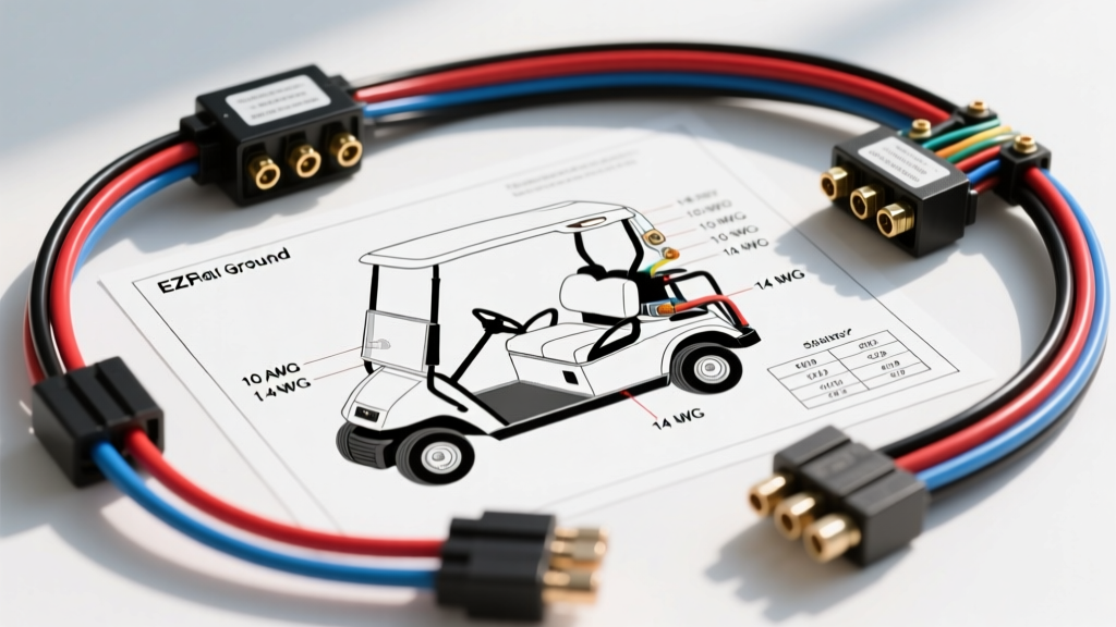
Introduction to EZGO Electrical Architecture
When diagnosing, repairing, or modifying fleet and personal utility vehicles, accessing an accurate ezgo golf cart wiring diagram is the foundational step for any electrical intervention. Unlike standard automotive 12-volt systems, golf carts operate on high-current, low-voltage DC architectures (36V and 48V) or high-frequency AC systems. This technical specification reference covers the primary electrical schematics for the ubiquitous EZGO TXT (DC series and SepEx) and the newer RXV (AC) platforms. All high-voltage routing and safety interlocks discussed herein adhere to the SAE International J2358 Standard for Low-Speed Vehicles, ensuring safe handling of traction battery circuits and motor controllers.
TXT Series DC Architecture: Solenoid and Controller Routing
The EZGO TXT platform, particularly the 48V DC models produced from 1995 to 2013, relies on a robust series-wound or separately excited (SepEx) DC motor paired with a heavy-duty main solenoid. The main solenoid acts as the primary high-current contactor, bridging the traction battery pack to the motor controller. In a standard 48V TXT wiring schematic, the main positive battery cable (2/0 AWG) routes to the solenoid's large top terminal, while the opposing large terminal routes directly to the B+ pin on the Curtis 1205 or 1206 motor controller.
Pre-Charge Circuit Dynamics
A critical component often missing from simplified diagrams is the pre-charge circuit. Across the large terminals of the main solenoid, a pre-charge resistor (typically 250 ohms, 2W) or a high-amperage diode is wired in parallel. When the solenoid engages, this circuit allows a trickle current to charge the main capacitors inside the motor controller before the heavy contacts close. Without this pre-charge resistor, the inrush current would cause severe arcing across the solenoid contacts, eventually welding them together and causing a runaway cart scenario. Always verify the integrity of this resistor when performing solenoid replacements.
Curtis 1205/1206 Motor Controller Pinout Specifications
The brain of the TXT DC system is the Curtis motor controller. Below is the standard pinout reference for the 48V SepEx configuration, which utilizes an Inductive Throttle System (ITS) rather than a traditional mechanical potentiometer.
| Pin / Terminal | Function | Wire Color | AWG Size |
|---|---|---|---|
| B+ (Main) | Positive Battery Input | Red | 2 AWG |
| B- (Main) | Negative Battery Return | Black | 2 AWG |
| M- (Motor) | Motor Armature Negative | Blue | 2 AWG |
| F1 / F2 | Motor Field Windings | Yellow / Green | 4 AWG |
| P1 (Solenoid) | Solenoid Coil Activation | Blue (18g) | 18 AWG |
| J1 (Throttle) | ITS Signal Input | White / Red / Black | 18 AWG |
| Interlock | Key Switch & Tow/Run | Red / Orange | 18 AWG |
Inductive Throttle System (ITS) Calibration and Wiring
Modern EZGO TXT carts utilize an ITS throttle box, which uses a magnetic hall-effect sensor rather than a physical wiper track. This eliminates the dead spots and erratic acceleration common in older V-glide potentiometers. The ITS wiring harness consists of three 18 AWG wires: a 5V reference (Red), a sensor ground (Black), and the signal return (White). When back-probing the signal wire with a digital multimeter (DMM), the voltage should read exactly 0.85V (+/- 0.05V) at the dead pedal position, and smoothly sweep to 4.20V at wide-open throttle. If the controller detects a voltage outside the 0.8V to 1.0V range upon key-up, it will trigger a High Pedal Disable (HPD) fault and prevent the solenoid from engaging.
RXV Series AC Drive System Wiring Differences
The introduction of the EZGO RXV marked a paradigm shift from DC to AC propulsion, utilizing a Danaher (later Dana) AC motor and controller. The EZGO Official Manufacturer Service Documentation outlines several fundamental wiring differences in the RXV schematic compared to the TXT:
- No Main Solenoid: The RXV AC controller handles high-current switching internally via solid-state IGBTs. The heavy 2/0 AWG cables route directly from the battery pack to the controller's B+ and B- terminals.
- Three-Phase Motor Wiring: Instead of armature and field wires, the AC motor uses three heavy-gauge phase wires (U, V, W), typically color-coded Yellow, Blue, and Red. Reversing the cart is achieved by the controller electronically swapping the phase sequence, eliminating the need for a mechanical Forward/Reverse (F&R) switch.
- Motor Encoder Harness: The AC motor relies on a 5-pin encoder to track rotor position. This requires a highly specific 18 AWG shielded cable. If the shield wire is not properly grounded to the controller chassis, electromagnetic interference (EMI) from the phase cables will corrupt the encoder signal, resulting in sudden motor rollback or controller lockouts.
Wire Gauge, Torque, and Terminal Specifications
High-amperage DC circuits are unforgiving of poor connections. A loose terminal on a 48V system pulling 300+ amps under load will generate immense heat, melting insulation and causing voltage drops that mimic a failing battery pack. Adhere strictly to the following torque specifications and gauge requirements when rebuilding an EZGO electrical system:
| Circuit Segment | Minimum AWG | Terminal Type | Torque Spec |
|---|---|---|---|
| Battery Pack Interconnects | 2/0 AWG | Heavy Duty Lugged | 120 in-lbs |
| Controller B+ / B- Main | 2 AWG | Ring Terminal | 90 in-lbs |
| Motor Phase / Armature | 2 AWG | Ring Terminal | 90 in-lbs |
| Solenoid Activation / ITS | 14-18 AWG | Spade / Push-on | Snug (15 in-lbs) |
Expert Note: Always apply a conductive anti-oxidant compound (such as No-Ox-Id A-Special) to all battery posts and high-current lugs before torquing. This prevents galvanic corrosion, which is the leading cause of voltage drop in 48V golf cart systems.
Onboard Computer (OBC) Bypass Wiring Modification
Many fleet operators and technicians opt to bypass the factory EZGO Onboard Computer (OBC) in favor of direct smart-charger integration. The OBC is a 6-pin module that regulates charging and controls the tow/run solenoid. To bypass the OBC in the wiring diagram:
- Disconnect the 6-pin OBC harness and remove the module.
- Locate the green wire in the main harness (charge relay activation) and connect it directly to the charger receptacle's positive trigger pin.
- Jump the tow/run solenoid activation wire directly to the key switch ignition source, ensuring the controller remains powered during storage without relying on the OBC's internal logic.
- Wire an aftermarket smart charger (e.g., Lester Summit Series) directly to the main battery pack positive and negative terminals, bypassing the cart's charging receptacle entirely to reduce resistance and heat.
Diagnostic Decision Tree: Solenoid Clicks but Cart Will Not Move
When referencing the wiring diagram to troubleshoot a 'click-no-go' scenario, follow this sequential multimeter diagnostic path:
- Step 1: Verify Pack Voltage. Measure across the main battery pack. A fully charged 48V pack should read 50.9V. If it reads below 46V under load, the controller's Low Voltage Cutoff (LVC) is active.
- Step 2: Solenoid Voltage Drop. Place DMM probes on the solenoid's two large terminals. Press the throttle. The meter should read 0.00V to 0.05V. A reading above 0.2V indicates welded or pitted internal contacts requiring solenoid replacement.
- Step 3: Controller B+ Input. Measure the B+ terminal on the motor controller relative to the B- terminal. It must match pack voltage. If voltage is missing here, trace the 2 AWG red cable back to the solenoid and check for a blown main fuse or severed crimp.
- Step 4: Motor Field/Armature Test. Disconnect the motor cables. Measure resistance across A1 and A2 (Armature). It should read near 0.00 ohms (continuity). Measure across S1 and S2 (Field). It should read between 2.0 and 5.0 ohms. An open circuit (OL) indicates a burnt motor winding.
For advanced controller parameter tuning, fault code extraction, and SepEx mapping, technicians should consult the Curtis Instruments 1205/1206 Controller Technical Manuals and utilize the Curtis 1311 handheld programmer to read real-time throttle mapping and thermal rollback thresholds.