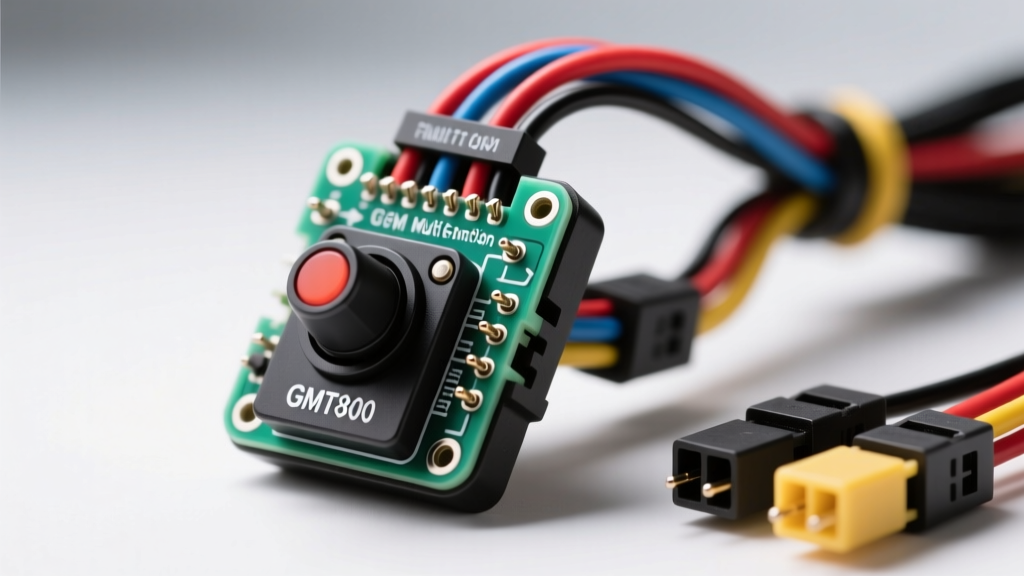
Decoding the Multi-Function Electrical Wiring Diagram Switch
When diagnosing steering column electrical faults, technicians often struggle with the complexity of the combination stalk. Unlike a simple single-pole toggle, a modern multi-function unit is a dense matrix of rotary and linear actuators. In this complete walkthrough, we will dissect the GMT800 (1999-2006 GM Silverado/Sierra) platform to understand how to read, trace, and test an electrical wiring diagram switch layout. By treating the switch not as a single component but as a network of logic gates and physical bridges, you can accurately diagnose hyper-flashing, dimmer failures, and wiper park issues without resorting to 'parts swapping'.
Understanding the Switch Architecture
The GMT800 multi-function switch (MFS) integrates turn signals, hazard flashers, high/low beam dimming, and wiper/washer controls into a single steering column stalk. From an electrical perspective, the electrical wiring diagram switch representation shows multiple discrete circuits sharing a common physical housing. The internal contacts are copper-alloy wipers that slide across a phenolic circuit board. Because these circuits handle relay trigger signals rather than high-amperage loads, the wiring relies on 18 AWG primary cables. Understanding this distinction is critical: the switch does not power the headlights directly; it triggers the Body Control Module (BCM) and underhood relays.
GMT800 14-Pin Connector Pinout & Wire Specification Chart
Before probing any wires, you must identify the correct pinouts. The main chassis-to-column bulkhead connector interfaces with the switch harness. Below is the reference chart for the standard 14-pin MFS connector, based on SAE J1128 standards for low-tension primary cable specifications.
| Pin | Wire Color | Circuit Function | AWG | Destination / Module |
|---|---|---|---|---|
| A | Purple | Turn Signal Feed (Flasher Out) | 18 | Hazard/Turn Flasher Module |
| B | Yellow | Left Turn Signal Output | 18 | BCM / Rear Junction Block |
| C | Dark Green | Right Turn Signal Output | 18 | BCM / Rear Junction Block |
| D | Light Blue | High Beam Relay Trigger | 18 | Underhood Bussed Electrical Center |
| E | Tan | Low Beam Relay Trigger | 18 | Underhood Bussed Electrical Center |
| F | Dark Green | Wiper Washer Pump Feed | 18 | Washer Motor / Ground |
| G | Gray | Wiper Motor High Speed | 18 | Wiper Motor Control Module |
| H | Purple | Wiper Motor Low Speed | 18 | Wiper Motor Control Module |
| J | Black | Switch Ground Reference | 16 | Steering Column Ground Splice |
| K | Brown | Hazard Switch Output | 18 | Hazard Flasher Module |
Circuit Walkthrough 1: Turn Signal and Hazard Matrix
The turn signal circuit is the most frequently serviced portion of the electrical wiring diagram switch. Power originates at the flasher module and travels via the Purple wire (Pin A) into the switch housing. When the lever is actuated left or right, an internal copper bridge connects Pin A to either Pin B (Yellow/Left) or Pin C (Dark Green/Right).
The Hazard Override Mechanism
What makes this diagram unique is the hazard override. The hazard button physically pushes a separator plate inside the switch housing. This breaks the connection between the turn signal flasher feed (Pin A) and the output pins, while simultaneously bridging the Hazard feed to both Yellow and Dark Green circuits. If your turn signals fail but hazards work, the electrical wiring diagram switch trace points directly to a failure in the Turn Signal Flasher Module or the Purple feed wire, not the stalk itself.
Circuit Walkthrough 2: Headlight Dimmer Relay Trigger
A common misconception among novice technicians is that the dimmer switch carries full headlight amperage (approx. 10-15 amps per bulb). If this were true, the electrical wiring diagram switch would require heavy 12 AWG or 10 AWG wiring. Instead, the GMT800 uses a relay-trigger architecture.
The headlight switch sends a 12V reference to the MFS. Inside the stalk, a linear actuator toggles between the Tan wire (Pin E - Low Beam) and the Light Blue wire (Pin D - High Beam). These 18 AWG wires route to the Underhood Bussed Electrical Center (UBEC) to energize the low-power coils of the headlight relays. If you have no low beams but high beams work, backprobe Pin E. If you read 12V at Pin E with the switch in the low-beam position, the switch is functioning perfectly, and the fault lies downstream in the UBEC relay or the Tan wire routing to the firewall.
Circuit Walkthrough 3: Wiper Park and Speed Logic
The wiper circuit within the electrical wiring diagram switch does not directly drive the wiper motor. Instead, it sends multiplexed resistance signals or discrete voltage triggers to the Wiper Motor Control Module (often integrated into the motor assembly on GMT800s). The Gray (Pin G) and Purple (Pin H) wires dictate high and low speed requests. The actual 'park' logic—ensuring the wipers return to the bottom of the windshield before shutting off—is handled by an internal park switch inside the wiper motor gearbox, completely independent of the column stalk. Diagnosing a 'wipers won't park' issue by replacing the column MFS is a classic misdiagnosis born from misunderstanding this diagram.
Diagnostic Testing: Probing the Switch Matrix
To properly test the switch, you must perform a voltage drop and continuity analysis. Follow these steps aligned with AutoShop 101 circuit testing guidelines:
- Access the Connector: Remove the steering column shroud using a T15 Torx driver. Disconnect the 14-pin bulkhead connector.
- Continuity Test (Power Off): Set your digital multimeter (DMM) to Ohms. Place one probe on Pin A (Purple) and the other on Pin B (Yellow). Actuate the left turn signal lever. You should see a drop to near 0.0 Ohms. If resistance fluctuates or reads above 2.0 Ohms, the internal copper wipers are worn or contaminated with dielectric grease and carbon dust.
- Voltage Drop Test (Live Circuit): Reconnect the harness. Use T-pin backprobes on Pin A and Pin B. Turn on the left turn signal. Measure the AC/DC voltage across the switch. A healthy switch will show a voltage drop of less than 0.1V when closed. A drop exceeding 0.5V indicates high internal resistance, which will cause hyper-flashing or BCM logic faults.
Physical Inspection & Connector Torque Specs
The physical environment of the steering column subjects the electrical wiring diagram switch harness to constant vibration and thermal cycling. According to SAE J1128, under-dash wiring must withstand temperatures up to 125°C, but the connector terminals are vulnerable to fretting corrosion.
- Shroud Fasteners: T15 Torx, torque to 2 Nm to prevent cracking the plastic column housing.
- Switch Mounting Screws: 2mm x 0.4 metric pan-head screws. Torque to 1.5 Nm. Over-tightening warps the phenolic circuit board inside the switch, causing the internal wipers to lose contact with the traces.
- Terminal Tension: If the bulkhead connector feels loose, do not rely on electrical tape. Use a terminal pick to gently bend the female terminal tangs outward to restore retention tension.
Common Failure Modes & The 'Melted Pigtail' Syndrome
While the switch handles mostly low-current signals, the Hazard and Turn Signal feeds can experience current spikes if a downstream short occurs and the BCM fails to limit current. A frequent failure mode on the GMT800 is the 'melted pigtail' at Pin A (Purple) and Pin K (Brown). This is rarely caused by the switch itself; rather, it is caused by high resistance at the flasher module socket or a corroded ground splice at the base of the A-pillar. The increased resistance generates heat (I²R losses), which travels down the wire and melts the plastic connector housing at the switch.
Repair Protocol: Never solder these repairs. Solder creates a rigid joint that will fatigue and break under steering column vibration. Always use a GM-approved pigtail repair kit with open-barrel crimps and adhesive-lined heat shrink tubing. For further guidance on proper crimping and relay testing, refer to the Haynes fuse and relay testing tutorials.
Summary
Mastering the electrical wiring diagram switch for the GMT800 multi-function stalk requires shifting your mindset from 'component replacement' to 'circuit tracing'. By understanding the relay-trigger architecture, respecting the 18 AWG signal limitations, and utilizing proper backprobing techniques, you can definitively isolate faults within the steering column matrix. Always verify the physical condition of the bulkhead connector and adhere to precise torque specifications to ensure long-term reliability of the repair.