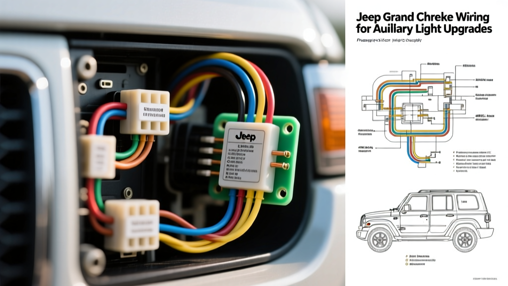
The Generational Divide: WJ vs. WK Electrical Architecture
When planning an off-road lighting modification, consulting a generic Jeep Grand Cherokee wiring diagram is a recipe for blown fuses or bricked control modules. The electrical architecture of the Grand Cherokee shifted drastically between the WJ generation (1999-2004) and the WK generation (2005-2010). Understanding this generational divide is the most critical step in your upgrade project. The WJ utilizes a traditional analog Power Distribution Center (PDC) and a standalone headlight switch, making auxiliary light integration relatively straightforward. In contrast, the WK introduced the Totally Integrated Power Module (TIPM), a highly sensitive, CAN-bus-integrated computer that manages exterior lighting via Pulse Width Modulation (PWM). Tapping into a WK lighting circuit without accounting for PWM will result in relay chatter, CAN-bus faults, and permanent TIPM damage.
Decoding the OEM Jeep Grand Cherokee Wiring Diagram
WJ (1999-2004) Power Distribution Center (PDC)
For WJ owners, the OEM wiring diagram routes headlight power through the under-hood PDC. The headlight switch sends a low-current signal to the multifunction switch, which then grounds the headlamp relays. To trigger an auxiliary light relay, you can safely tap into the OEM low-beam circuits. The Left Low Beam wire is typically White/Tan, and the Right Low Beam is White/Dark Green. Using a Posi-Tap connector, you can pull a 12V DC trigger signal directly from these circuits to activate your aftermarket relay coil without overloading the OEM multifunction switch.
WK (2005-2010) Totally Integrated Power Module (TIPM)
The WK generation eliminated traditional fuses and relays for exterior lighting, replacing them with solid-state drivers inside the TIPM. The TIPM monitors the resistance of the lighting circuits. If you splice a standard relay coil directly into a WK headlight wire, the TIPM will read the added inductance as a short circuit or bulb failure, triggering a diagnostic trouble code (DTC) and shutting off power to the circuit entirely.
Wire Gauge and Overcurrent Protection Specifications
Off-road LED light bars and HID spotlights draw significant current. Relying on OEM wiring to carry auxiliary loads violates SAE J1128 standards for low-tension automotive wire. You must run dedicated power and ground lines from the battery to the auxiliary lights, using an ISO mini relay to handle the heavy switching. Use SAE-approved GXL or TXL cross-linked polyethylene wire for under-hood routing to resist heat and abrasion.
| Total Lighting Load (Watts) | Current Draw @ 14.4V | Recommended AWG Size | Inline Fuse Rating |
|---|---|---|---|
| 50W (Single LED Pod) | 3.5 Amps | 16 AWG | 5A Blade |
| 100W (Dual LED Pods) | 7.0 Amps | 14 AWG | 10A Blade |
| 200W (20-inch Light Bar) | 14.0 Amps | 10 AWG | 20A Blade |
| 400W+ (50-inch Light Bar) | 28.0+ Amps | 8 AWG | 40A ANL/MIDI |
The WK PWM Headlight Circuit Challenge
If you are modifying a WK Grand Cherokee, you cannot use the headlight wires as a relay trigger. The TIPM outputs a PWM signal to the headlights to monitor bulb health and extend bulb life. A PWM signal rapidly cycles 12V on and off. Feeding this into a standard electromechanical relay coil will cause the relay to chatter violently, generating excessive heat and failing prematurely. To solve this, WK owners have two options: purchase an aftermarket PWM-to-DC signal converter, or bypass the headlight trigger entirely. The preferred expert method is to tap a dedicated 12V Fused Ignition Run/Start circuit in the TIPM (such as the F20 or F34 cavity), route it through a secondary manual switch or an upfitter switch on the dash, and use that to trigger the relay coil.
Standard ISO Relay Pinout and Integration
For both WJ and WK applications, a standard Bosch-style ISO mini relay (30/40 Amp) is the industry standard for switching high-current auxiliary lighting. Below is the standard pinout configuration for your wiring harness.
| Relay Pin | Function | Standard Wire Color | Connection Point |
|---|---|---|---|
| Pin 30 | Common (Power In) | Red (Heavy Gauge) | Positive Battery Terminal (via inline fuse) |
| Pin 87 | Normally Open (Load) | Red (Heavy Gauge) | Positive Input of Auxiliary Lights |
| Pin 85 | Coil Ground | Black (18 AWG) | Clean Chassis Ground or Battery Negative |
| Pin 86 | Coil Trigger (12V+) | Yellow/Blue (18 AWG) | OEM Headlight Tap (WJ) or Dash Switch (WK) |
| Pin 87a | Normally Closed | Not Used | Cut and heat-shrink to prevent shorts |
Step-by-Step Tapping and Routing Procedures
- Disconnect the Battery: Always isolate the negative terminal before cutting or splicing any OEM harnesses to prevent CAN-bus spikes.
- Route the Main Power: Run your primary 10 AWG or 8 AWG power wire through the firewall grommet or along the frame rail, keeping it at least 6 inches away from exhaust manifolds and steering shafts.
- Install the Inline Fuse: Place the main fuse within 18 inches of the battery positive terminal. This protects the entire wire run in the event of a chafing short.
- Establish a Star Ground: Do not ground the relay or the lights to random sheet metal. Locate a factory grounding stud on the chassis or engine block. Remove the factory nut, clean the surface with a wire brush, attach your aftermarket ground ring terminal, and secure it using a star washer to bite through any corrosion or paint.
- Seal all Connections: Use marine-grade heat shrink with adhesive lining. Apply dielectric grease to all OEM connectors you have tapped into to prevent galvanic corrosion.
Troubleshooting Common Aftermarket Lighting Failures
Even with a flawless Jeep Grand Cherokee wiring diagram reference, environmental factors and hidden module logic can cause issues. Here is how to diagnose common modification failures:
- Relay Chatter on WK Models: If your relay clicks rapidly and the lights flicker, you have tapped into a PWM-controlled circuit. Install a PWM filter capacitor or reroute the trigger wire to an ignition-switched 12V source.
- TIPM Lockout (No Power at Tap): If the TIPM detects an anomaly during the initial install (such as a momentary short while stripping wires), it will hard-lock the circuit. Disconnect the battery for 15 minutes to force a TIPM hard reset and clear the volatile memory fault.
- Voltage Drop at the Lights: If your 400W light bar is dimming after 5 minutes of use, measure the voltage at the battery and then at the light connector under load. If the difference exceeds 0.5V, your AWG wire gauge is too small, or your chassis ground is corroded. Upgrade to 8 AWG wire and re-terminate the ground.
- Backfeed through the Multifunction Switch: On WJ models, if the aux lights turn on but the OEM dash indicators flicker, you have a backfeed issue. Ensure you are using a diode in the trigger line or tapping on the load side of the OEM headlamp relay, not the switch side.
Authoritative References
For deeper integration into the CAN-bus network and advanced upfitter protocols, always consult official documentation. We highly recommend referencing the Haynes Automotive Manuals for generation-specific connector pinouts, and reviewing Mopar Service Tips for the latest technical service bulletins (TSBs) regarding TIPM replacements and grounding procedures. Adhering to SAE J1128 wiring standards ensures your modification remains safe, reliable, and road-legal.