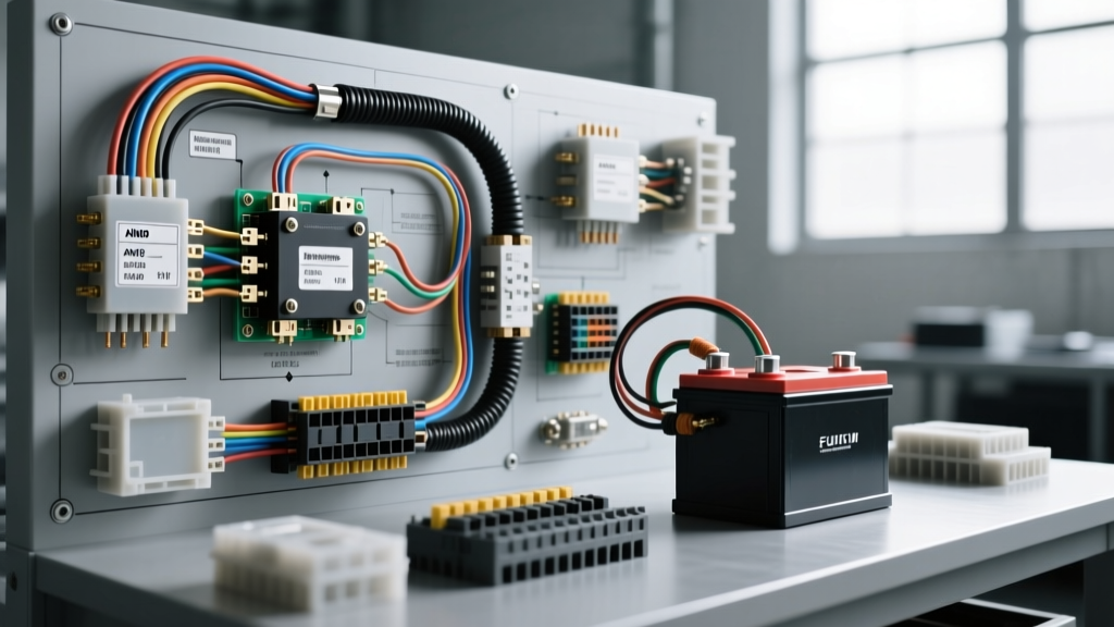
The Shift to LiFePO4: Why Your RV Wiring Needs an Overhaul
Upgrading an RV or camper van from legacy AGM or flooded lead-acid batteries to a Lithium Iron Phosphate (LiFePO4) house bank is one of the most impactful modification projects you can undertake. However, lithium batteries demand a completely different approach to electrical architecture. They accept charge currents much faster, require precise low-voltage disconnects, and generate massive fault currents if short-circuited. When interpreting a standard wiring diagram rv battery hook up picture, the most critical junction is the main DC busbar and the battery management system (BMS) integration. This guide translates visual schematics into actionable, high-amperage mechanical steps for a safe, high-performance RV electrical system.
Decoding the RV Battery Hook Up Wiring Diagram & Picture Layout
Most generic diagrams fail to show the physical routing and sequential order of connections. A professional-grade wiring diagram rv battery hook up picture follows a strict left-to-right logical flow to minimize voltage drop and ground loops. Here is the visual breakdown of the optimal topology:
- Node 1 (Input): Solar Array routing through a bulkhead gland into a DC breaker, then to the MPPT Solar Charge Controller (SCC).
- Node 2 (Distribution): SCC output connects to the Positive and Negative DC Busbars. The busbars act as the central nervous system, preventing daisy-chaining on battery terminals.
- Node 3 (Storage): The LiFePO4 battery bank connects to the busbars. A main Class T fuse is placed on the positive trunk within 7 inches of the battery terminal.
- Node 4 (Monitoring): A 500A/50mV battery monitor shunt is installed on the negative main trunk, between the negative busbar and the battery bank.
- Node 5 (Output): The Inverter/Charger draws directly from the busbars, protected by its own dedicated ANL or Class T fuse.
According to the Victron Energy Wiring Unlimited Manual, keeping the positive and negative cables routed together (but not overlapping) reduces electromagnetic interference (EMI) and inductance, which is vital for sensitive inverter logic boards.
Critical Component Specifications & Wire Sizing Chart
Selecting the correct American Wire Gauge (AWG) and overcurrent protection is non-negotiable. LiFePO4 batteries can output 200A+ continuously; undersized wires will melt, and incorrect fuses will nuisance-trip or fail to clear a fault. Use 600V SGR/SGT fine-stranded copper battery cable for all main trunks.
| Circuit Segment | Max Continuous Load | Recommended AWG | Fuse Type & Rating | Lug / Terminal Size |
|---|---|---|---|---|
| Battery to Busbar (Main Trunk) | 300A | 2/0 AWG | Class T (400A) | 3/8" Ring Terminal |
| Inverter to Busbar (2000W-3000W) | 250A | 2/0 AWG | Class T (300A) | 3/8" Ring Terminal |
| MPPT SCC to Busbar (100A Output) | 100A | 2 AWG | ANL (150A) | 5/16" Ring Terminal |
| DC Fuse Box to Busbar | 60A | 6 AWG | ANL (80A) | 5/16" Ring Terminal |
| BMS Communication / Shunt | < 1A | 16 AWG (Shielded) | Inline 5A ATC | Ferrule / RJ45 |
Step-by-Step Execution: Routing and Terminating the Main Trunks
1. Crimping and Heat Shrinking
Never use solder on high-amperage RV battery cables. Solder can become brittle under chassis vibration and has a lower melting point than copper, leading to catastrophic joint failure during a fault. Instead, use a hex-crimp tool (like the Temco TH-396) to compress closed-end copper lugs onto your 2/0 AWG cable. After crimping, apply 3:1 ratio adhesive-lined marine heat shrink. The adhesive lining melts and seals the wire strands, preventing galvanic corrosion and moisture ingress—a common failure point in humid RV environments.
2. Busbar Mounting and Torque Specifications
Mount your positive and negative busbars at least 4 inches apart to prevent accidental tool shorting. Use Tinned Copper Busbars rated for minimum 600A. When securing the 3/8" ring terminals to the M8 stainless steel studs, use a calibrated torque wrench. The Blue Sea Systems Circuit Protection Guide emphasizes that undertorquing creates micro-gaps that increase resistance and generate heat. Over-torquing stretches the stud, reducing clamping force over time. Set your torque wrench to exactly 4.5 Nm (40 in-lbs) for standard M8 busbar studs.
BMS Integration and Shunt Calibration
Modern LiFePO4 batteries feature an internal Battery Management System (BMS) that monitors cell voltage, temperature, and current. While the internal BMS protects the cells, it does not provide real-time state-of-charge (SoC) data to your RV's control panel. This requires a precision shunt.
Wiring the 500A/50mV SmartShunt
- Placement: The shunt must be the only component on the negative side connected directly to the battery bank. All other negative loads and grounds must terminate on the negative busbar.
- VE.Direct Routing: Run the VE.Direct communication cable to your solar charge controller or Bluetooth module. Keep this data cable at least 2 inches away from the 2/0 AWG positive cables to prevent signal noise.
- Auxiliary Battery Input: If you are monitoring a starter battery or a secondary bank, use the 16 AWG shielded auxiliary wire connected to the shunt's M8 auxiliary terminal.
Common Modification Mistakes & Troubleshooting
Even with a perfect wiring diagram rv battery hook up picture, execution errors can cripple your system. Here is how to troubleshoot the most common DIY modification failures:
Symptom: Inverter Shuts Down Under Heavy Load (Voltage Sag)
- Cause: Excessive voltage drop across the DC busbars or main cables. LiFePO4 batteries maintain a flat voltage curve (around 13.4V), but if your cables are too long or undersized, the inverter may 'see' 10.5V at its terminals and trigger a low-voltage disconnect.
- Fix: Perform a millivolt drop test. Set your multimeter to DC millivolts. Place the probes across each connection point (e.g., battery terminal to fuse, fuse to busbar) while the inverter is under load. Any single connection showing a drop greater than 10mV needs to be disassembled, cleaned with a wire brush, and retorqued.
Symptom: Solar Charge Controller Throws 'High Voltage' Error
- Cause: The BMS has internally disconnected the charge MOSFETs due to a cell over-voltage or low-temperature cutoff, but the MPPT controller is still pushing current into the busbar, causing system voltage to spike.
- Fix: Wire a BMS communication relay or use a charge controller with a dedicated BMS CAN-bus/RS485 input. This allows the battery to physically signal the MPPT to halt charging before the internal contactors open, protecting your RV's sensitive electronics from voltage transients.
Final Safety Inspections
Before energizing the system, double-check all polarity with a multimeter. Ensure all Class T and ANL fuse caps are securely fastened, and verify that no stray wire strands are protruding from your crimped lugs. For comprehensive standards on DC wiring in mobile environments, refer to the Battle Born Batteries RV Wiring Guide and NFPA 1192 (Standard for Recreational Vehicles). A properly executed lithium upgrade will not only provide days of off-grid boondocking but will do so with absolute electrical safety and efficiency.