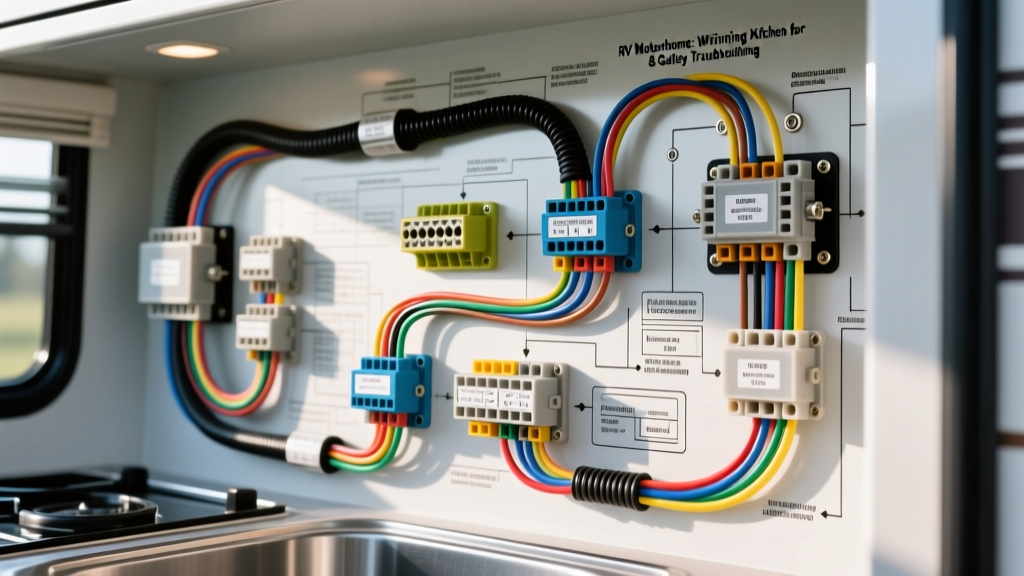
Understanding the RV Galley Electrical Architecture
When diagnosing electrical faults in a motorhome or expedition vehicle, the galley presents a unique challenge. Unlike standard automotive cabin wiring, an RV kitchen integrates high-amperage 12V DC coach systems with 120V AC residential appliances. Interpreting an OEM wiring diagram for kitchen nodes requires a technician to seamlessly transition between chassis-grade DC logic and shore-power AC schematics. This guide provides a step-by-step troubleshooting flow for the most common galley electrical failures, referencing RV Industry Association (RVIA) standards and SAE J1128 low-tension primary cable specifications.
12V DC Coach Systems vs. 120V AC Appliances
Before diving into the troubleshooting decision tree, it is critical to map the power distribution. The typical RV kitchen circuit relies on a dual-voltage architecture:
- 12V DC Systems (Coach Battery Bank): Powers the water pump (typically 10A), LED under-cabinet lighting, range hood exhaust fan, and the logic/control board of absorption refrigerators.
- 120V AC Systems (Shore Power / Inverter): Powers residential refrigerators, induction cooktops, microwaves, and galley GFCI receptacles. These are routed through an automatic transfer switch (ATS) and a 3000W+ pure sine wave inverter.
Step-by-Step Troubleshooting Flow for Kitchen Circuits
Use the following symptom-based decision trees to isolate faults. Always verify battery state-of-charge (SOC) and shore-power pedestal voltage before proceeding.
Symptom 1: 12V DC Absorption Fridge Control Board is Dead
Context: The Dometic or Norcold RV fridge requires a steady 12V DC supply to power the logic board, even when operating on LP gas or 120V AC heating elements. If the display is blank, follow this flow:
- Step 1: Check the DC Main Fuse. Locate the coach distribution panel. Verify the 15A ATC blade fuse for the "Refrigerator DC" circuit. If blown, check for a shorted heating element wire chafing against the chassis frame.
- Step 2: Measure Voltage at the Terminal Block. Disconnect the 4-pin Molex connector at the rear of the fridge. Using a digital multimeter (DMM), probe the 12V+ (Red) and Ground (White) wires. Specification: You must read a minimum of 10.5V DC. If voltage is below 10.5V, the logic board will not initialize.
- Step 3: Calculate Voltage Drop. If the battery reads 12.6V but the fridge connector reads 10.2V, you have excessive voltage drop. According to RVIA Low Voltage Standards, DC voltage drop should not exceed 3%. Inspect the chassis ground lug near the galley floor for corrosion. Clean with a wire brush and retorque to 12 Nm.
- Step 4: Verify the Ignition Sense Wire. Pin 3 on the fridge connector (Yellow, 16 AWG) signals the fridge to shut off when the engine is running to prevent battery drain. If this wire is shorted to ground, the fridge will remain permanently disabled.
Symptom 2: 120V AC Induction Cooktop Fails on Inverter Power
Context: The Furrion or Dometic induction cooktop operates flawlessly on shore power but trips the inverter or shuts down when running off-grid.
- Step 1: Analyze the Inverter Surge Rating. An induction cooktop draws roughly 1500W (12.5A at 120V AC). However, the initial capacitor charge and EMI filter engagement can cause a 50-millisecond surge of up to 30A. Verify the inverter's surge rating exceeds 3000W. If it is a 2000W inverter, it will fault on over-current.
- Step 2: Inspect the AC Wire Gauge. Trace the 120V AC feed from the inverter sub-panel to the cooktop. It must be 12 AWG THHN stranded copper, protected by a 20A hydraulic-magnetic breaker. If a previous technician used 14 AWG wire, the voltage drop under load will cause the cooktop's internal low-voltage cutoff to trigger.
- Step 3: Check for Shared Neutral Faults. In multi-wire branch circuits (MWBC) common in RV kitchens, a shared neutral can become overloaded if both the microwave and cooktop are on the same inverter phase, causing the neutral bus to overheat and the GFCI to trip.
Symptom 3: Galley GFCI Trips When 12V Water Pump Engages
Context: This is a notorious RV-specific ghost fault. The 120V AC GFCI receptacle near the sink trips exactly when the 12V DC Shurflo water pump turns on.
- Step 1: Identify EMI/RFI Interference. Universal motors in 12V water pumps generate severe electromagnetic interference (EMI) via brush arcing. This high-frequency noise can couple into the 120V AC wiring harness, tricking the GFCI's internal toroidal sensor into detecting a false 5mA ground fault.
- Step 2: Isolate the Wiring Harness. Consult the Winnebago Technical Information schematics or your specific OEM manual to trace the wire routing. The 12V DC pump wires and 120V AC GFCI wires must never be bundled in the same loom or zip-tied together behind the galley cabinetry.
- Step 3: Install a Ferrite Choke. If rerouting is impossible, snap a ferrite bead (impedance >150 ohms at 100MHz) onto the 12V DC positive wire as close to the pump motor as possible to suppress high-frequency noise.
- Step 4: Verify Ground Isolation. Ensure the 12V DC water pump ground is tied to the main DC ground bus, NOT to the AC chassis ground or the plumbing pipes. A shared ground path will inject DC ripple directly into the GFCI sensing circuit.
RV Kitchen Wiring Specification Chart
Adhering to proper AWG sizing and RVIA color codes is mandatory for safety and passing DOT/RVIA inspections. Reference this chart when repairing or extending galley circuits.
| Application | Voltage | Wire Gauge (AWG) | RVIA Wire Color Code | Overcurrent Protection |
|---|---|---|---|---|
| 12V DC Water Pump | 12V DC | 12 AWG (SAE GXL) | Black (Hot), White (Ground) | 15A ATC Blade Fuse |
| Fridge Logic Board | 12V DC | 10 AWG (SAE GXL) | Red (Hot), White (Ground) | 15A ATC Blade Fuse |
| Induction Cooktop | 120V AC | 12 AWG (THHN Stranded) | Black (Hot), White (Neutral), Green (Earth) | 20A Hydraulic-Magnetic Breaker |
| Galley GFCI Receptacle | 120V AC | 12 AWG (THHN Stranded) | Black (Hot), White (Neutral), Bare (Earth) | 20A GFCI Breaker or Receptacle |
| Range Hood / Vent Fan | 12V DC | 16 AWG (SAE GXL) | Yellow (Hot), White (Ground) | 5A Mini Fuse |
Decoding the OEM Wiring Diagram for Kitchen Nodes
When reading factory schematics for the galley, you will encounter specific connector types and pinout configurations. Understanding these is crucial for tracing continuity faults without back-probing and damaging delicate logic boards.
Common Galley Connectors
- Molex Mini-Fit Jr. (4-Pin): Standard for RV refrigerator DC inputs. Pin 1: 12V+ (Red), Pin 2: Ground (White), Pin 3: Ignition Sense (Yellow), Pin 4: Data/Comm (Green).
- Deutsch DT Series (2-Pin): Used for high-current 12V DC appliances like the water pump and exterior kitchen speakers. Features silicone seals to prevent moisture ingress from galley sink splashes.
- WAGO Lever-Nuts (221 Series): Increasingly used by OEMs for 120V AC junction boxes behind the galley cabinetry instead of traditional wire nuts, providing vibration-resistant connections that comply with RVIA 2023 vibration testing standards.
Troubleshooting the Range Hood Micro-Switches
The range hood light and fan are often controlled by low-voltage micro-switches on the control panel, which trigger a 12V DC relay located in the main distribution panel. If the fan does not spin but the light works, do not immediately replace the motor. First, locate the 12V relay in the galley overhead cabinet. Use a DMM to verify that the coil is receiving 12V+ on terminal 86 and a solid ground on terminal 85 when the switch is pressed. If the relay clicks but the fan is dead, probe terminal 87 for 12V+ output. A lack of voltage here indicates pitted internal relay contacts, a common failure mode due to the inductive kickback of the fan motor lacking a flyback diode.
Final Diagnostic Verification
After executing the repairs outlined in this troubleshooting flow, always perform a load test. Turn on the 120V AC induction cooktop, engage the 12V DC water pump, and switch the refrigerator to AUTO mode simultaneously. Monitor the DC bus voltage at the main coach battery terminals; it should not drop below 11.8V under this combined load. Finally, use an infrared thermometer to scan the galley distribution panel and GFCI receptacles after 15 minutes of operation. Any terminal reading more than 20°F above ambient room temperature indicates a high-resistance connection requiring immediate termination replacement.