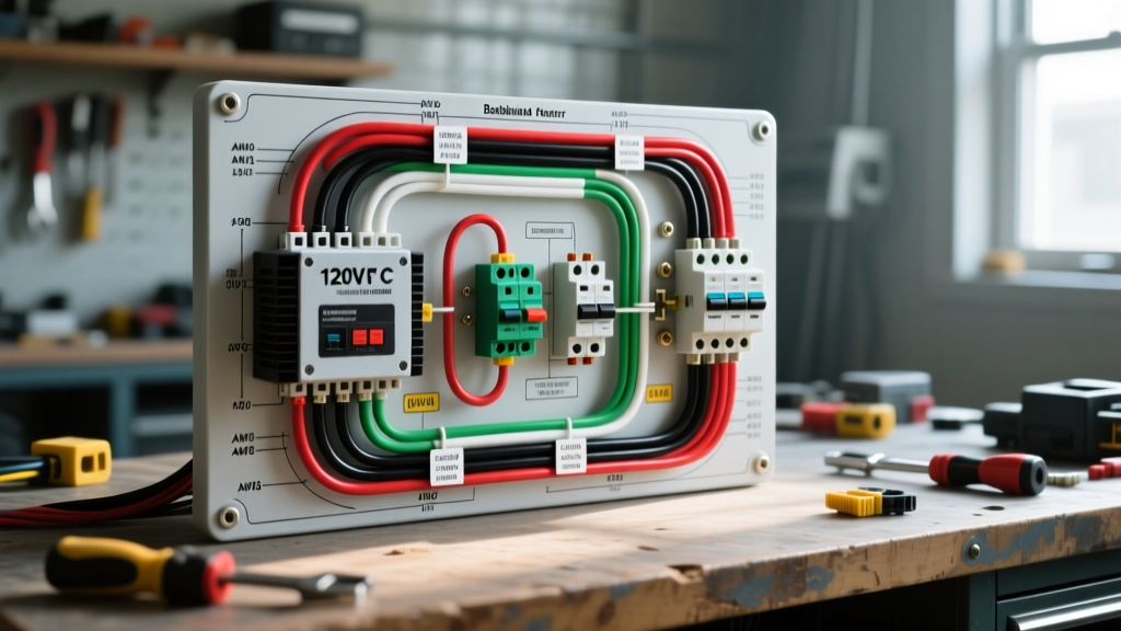
The Architecture of 120V AC Heating in Class A Motorhomes
Integrating a residential-style 120V AC electric baseboard heater into a Class A motorhome, custom Sprinter van conversion, or fifth-wheel RV requires bridging residential HVAC concepts with strict SAE automotive electrical standards. While searching for a standard baseboard heater wiring diagram will yield excellent results for stationary homes, applying those exact schematics to a mobile, high-vibration, dual-power-source (shore/generator vs. inverter) environment is a recipe for catastrophic failure. Resistive heating elements draw massive continuous current, and in an RV, this current must often be inverted from a 12V, 24V, or 48V DC lithium battery bank.
This advanced technical guide dissects the precise wiring topology, wire gauge requirements, load-shedding relay logic, and chassis bonding protocols necessary to safely install and operate a 1500W to 2000W 120V AC baseboard heater in a recreational vehicle. We will reference NFPA 1192 Standard on Recreational Vehicles and SAE J1113 Electromagnetic Compatibility guidelines throughout this deep dive.
DC-to-AC Inversion: Sizing the Power Source
A standard 1500W baseboard heater draws approximately 12.5 Amps at 120V AC. However, the DC side of the circuit tells a vastly different story. When factoring in an inverter efficiency rating of roughly 92%, the DC current draw from a 12V nominal battery bank (operating at 12.8V under load) exceeds 130 Amps continuously. Using standard automotive wire for this DC feed will result in severe voltage drop, thermal runaway, and melted insulation.
DC Feed Specifications & Torque Requirements
For a 1500W baseboard heater operating via a 12V DC system, the following DC-side specifications are mandatory:
- Wire Gauge: 2/0 AWG (00 AWG) stranded copper welding cable or Type MTW. Solid copper wire is strictly prohibited in RV applications due to chassis vibration causing work-hardening and eventual fracture.
- Overcurrent Protection: 150A Class T fuse mounted within 7 inches of the battery positive terminal. Standard ANL fuses do not possess the adequate interrupting capacity (AIC) for high-ampacity lithium battery banks.
- Terminal Torque: Inverter DC busbar lugs must be torqued to exactly 15 Nm (11 ft-lbs) using a calibrated torque wrench. Under-torqued 2/0 AWG lugs will arc and carbonize under the 130A continuous load.
AC Sub-Panel Routing and the Baseboard Heater Circuit
Once the DC power is cleanly inverted to a pure sine wave 120V AC output, the AC distribution must be managed through a dedicated sub-panel or a specialized inverter-backed critical loads panel. According to Victron Energy inverter integration manuals, high-draw resistive loads should ideally be isolated from sensitive electronics to prevent harmonic distortion or voltage sag during thermostat cycling.
AC Wire Sizing Chart for Baseboard Heaters
| Heater Wattage | AC Amperage (120V) | Min. AC Wire Gauge (Stranded) | Breaker Size | Max Run Length (3% Drop) |
|---|---|---|---|---|
| 1000W | 8.3A | 14 AWG THHN | 15A Single Pole | 45 Feet |
| 1500W | 12.5A | 12 AWG THHN | 20A Single Pole | 40 Feet |
| 2000W | 16.6A | 10 AWG THHN | 25A Single Pole | 35 Feet |
Note: All AC wiring in the RV must be stranded copper (THHN/THWN-2). Standard residential Romex (NM-B) with solid conductors is a severe code violation in mobile platforms and will fail at the terminal screws due to road-induced micro-vibrations.
Load-Shedding Relay Logic: Preventing Inverter Faults
The most common failure mode in RV baseboard heater installations is inverter overload. If the RV's roof air conditioning compressor kicks on while the baseboard heater is actively drawing 1500W, the combined surge and continuous load will exceed the 3000W inverter's limit, triggering an immediate low-voltage or over-current shutdown. To prevent this, we implement an automated load-shedding circuit using a heavy-duty 12V DC relay or contactor.
Bosch-Style 5-Pin Relay Pinout for Load Shedding
Wire a standard ISO mini relay (or a heavy-duty contactor for loads exceeding 30A) to interrupt the baseboard heater's 120V AC hot leg whenever the AC compressor clutch engages.
- Pin 30 (Common): Connect to the 120V AC Inverter Output (Hot Leg).
- Pin 87 (Normally Open): Connect to the Baseboard Heater Thermostat/Element (Hot Leg).
- Pin 87a (Normally Closed): Not used in this shedding configuration; cap and insulate.
- Pin 86 (Coil +): Connect to a 12V DC ignition or accessory circuit that is NOT active when the AC compressor is running, or wire to the inverse of the AC compressor clutch signal.
- Pin 85 (Coil -): Connect to a clean 12V DC chassis ground.
By wiring the relay coil to activate only when the generator or shore power is active, or by using a current-sensing relay on the AC bus, the baseboard heater is automatically disabled during off-grid inverter operation or when high-surge appliances cycle on.
Thermostat Integration: Line-Voltage vs. Low-Voltage Control
Residential baseboard heaters typically utilize line-voltage thermostats, meaning 120V AC passes directly through the thermostat's bimetallic switch. In an RV environment, routing 120V AC across the living space to a wall-mounted thermostat introduces unnecessary shock hazards and EMI (Electromagnetic Interference) risks.
The Expert Solution: Utilize a low-voltage (24V AC or 12V DC) smart thermostat wired to a 120V AC definite-purpose contactor mounted directly adjacent to the baseboard heater. This keeps high-voltage AC confined to a single, localized junction box near the floorboards, while only low-voltage control wires run through the RV's walls to the thermostat. This methodology strictly adheres to SAE J1113 guidelines for minimizing high-voltage cable runs in mobile cabins.
Grounding, Bonding, and GFCI Protection
Grounding a 120V AC baseboard heater in a vehicle is fundamentally different from grounding it in a house. In a residence, the ground is tied to a copper rod driven into the earth. In an RV, the ground must be tied to the vehicle's steel chassis, and the inverter's internal Neutral-Ground (N-G) bond must be managed correctly depending on the power source.
The Neutral-Ground Bonding Dilemma
- Shore Power Mode: The RV's transfer switch must isolate the inverter's N-G bond. The ground reference is provided by the shore power pedestal. The baseboard heater's ground wire (Green/Bare) connects to the AC sub-panel ground bus, which is bonded to the RV chassis.
- Inverter Mode: The inverter must internally create the N-G bond. If your inverter lacks an automatic N-G bonding relay, you must install an external ground relay to bond the neutral and ground buses when operating off-grid. Without this bond, a ground fault in the baseboard heater will not trip the GFCI breaker, posing a lethal electrocution hazard in the damp environment of an RV.
Mandatory Protection: Because baseboard heaters are often installed near the floor where moisture from wet boots or pets can accumulate, the circuit must be protected by a 20A GFCI (Ground Fault Circuit Interrupter) breaker at the sub-panel, not just a standard thermal breaker.
Troubleshooting Matrix: Real-World RV Heating Failures
When a baseboard heater fails to operate or trips the inverter in a motorhome, use this diagnostic decision tree to isolate the fault.
| Symptom | Probable Cause | Diagnostic Action & Fix |
|---|---|---|
| Inverter faults (Overload) immediately upon thermostat click. | Heater element shorted, or incorrect inverter sizing. | Disconnect heater. Measure element resistance with multimeter. A 1500W element should read ~9.6 Ohms. If near 0 Ohms, replace element. |
| Heater works on shore power, but not on inverter. | Transfer switch failure or Load-Shedding relay stuck open. | Verify 120V AC at Pin 30 of the shedding relay. Check 12V DC coil voltage. Bypass relay temporarily to confirm. |
| Heater cycles rapidly; wires in junction box are hot to touch. | Voltage drop due to undersized AC wire over long RV wheelbase. | Measure AC voltage at the heater terminals under load. If below 110V, upgrade from 12 AWG to 10 AWG stranded THHN to reduce resistance. |
| GFCI breaker trips randomly while driving. | Chassis vibration causing neutral wire to chafe against ground. | Inspect all wire runs passing through bulkheads. Apply grommets and secure with adhesive-lined heat shrink and cable ties per NFPA 1192. |
Final Commissioning and Thermal Imaging
After completing the baseboard heater wiring diagram integration, do not simply button up the walls and panels. Run the heater at maximum capacity for 60 minutes while operating solely on inverter power. Use a FLIR thermal imaging camera to scan the inverter DC lugs, the Class T fuse, the AC sub-panel breakers, and the load-shedding relay terminals. Any terminal showing a temperature delta greater than 15°C (27°F) above ambient indicates a high-resistance connection requiring immediate re-termination and re-torquing. Only through rigorous adherence to these mobile-specific electrical standards can you ensure safe, reliable, and efficient resistive heating in your recreational vehicle.