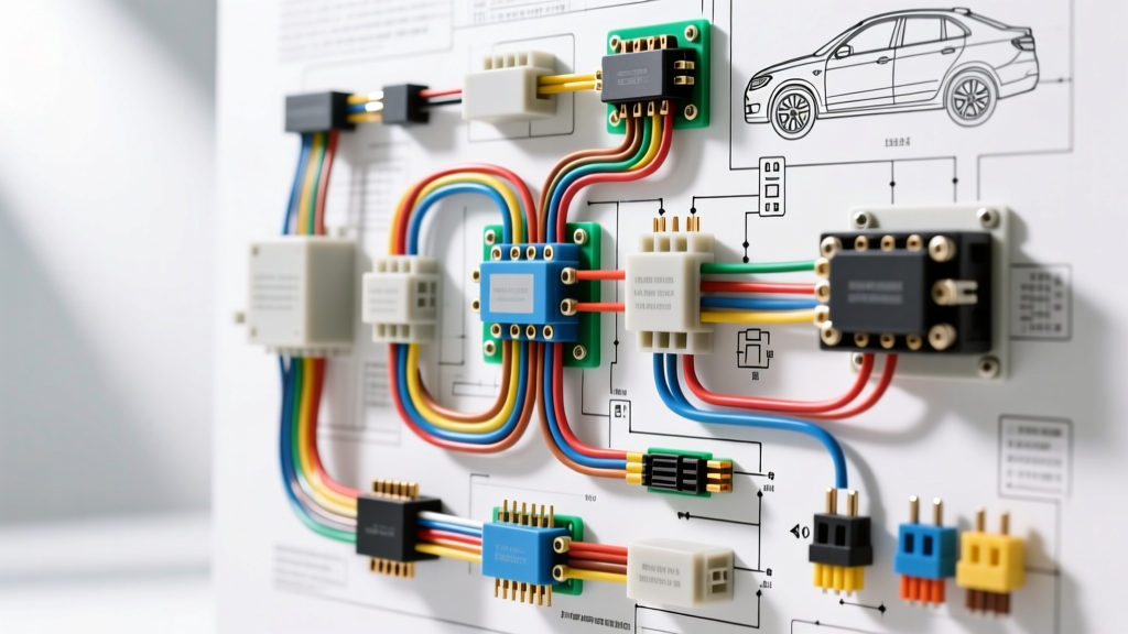
Introduction to Automotive Electrical Schematics
Modern vehicles are essentially rolling networks of computers, sensors, and high-current loads. When diagnosing an electrical fault, guessing is not an option; you need a precise roadmap. Understanding how to read a wiring diagram for cars is the single most critical skill an automotive technician or DIY enthusiast can develop. Unlike basic block diagrams that show general component relationships, OEM-level schematics detail exact wire colors, American Wire Gauge (AWG) sizes, splice pack locations, and connector cavity pinouts.
In this complete walkthrough, we will dissect the anatomy of a factory wiring diagram. We will trace a complete circuit from the battery positive (B+) feed through a relay, into a high-current load, and back to the chassis ground. By the end of this guide, you will be able to navigate complex OEM schematics, identify standard SAE symbols, and perform targeted electrical diagnostics.
Step 1: Decoding Standard Schematic Symbols
Before tracing a single wire, you must understand the visual language of the schematic. Most North American and European manufacturers adhere to standards outlined by SAE International (specifically J1135) or DIN/ISO standards for symbol representation.
Power Sources and Grounds
- Battery Feed (B+): Represented by a straight line pointing to a battery symbol, often labeled with a fuse number and amperage (e.g., 'FUSE 42 20A'). This indicates constant battery voltage.
- Ignition Feed (IGN): Usually depicted with a key cylinder symbol, indicating power is only present in the 'Run' or 'Start' positions.
- Chassis Ground (GND): Shown as three descending horizontal lines. The diagram will provide a specific ground node identifier (e.g., 'G102' or 'Z1'), which corresponds to a physical bolt location on the vehicle body or engine block.
Switches, Relays, and Solenoids
Relays are the workhorses of automotive high-current circuits. In a wiring diagram for cars, a standard ISO/DIN 5-pin relay is drawn as a box with a coil and a switch. The terminals follow the DIN 72552 standard:
- Pin 30: Common power input (from battery/fuse).
- Pin 87: Normally Open (NO) output to the load.
- Pin 87a: Normally Closed (NC) output (used in dual-circuit relays).
- Pin 86: Coil power input (usually switched 12V from a BCM or dash switch).
- Pin 85: Coil ground (often controlled by a module via a low-side driver).
Step 2: Understanding Wire Color Codes and AWG
Wires on a schematic are represented by lines, with alphanumeric codes printed along the path. The first part of the code dictates the base color, the second dictates the tracer (stripe) color, and the final number indicates the wire gauge or metric cross-sectional area.
For example, a wire labeled RD/VT 10 means it is a 10 AWG wire with a Red base and a Violet tracer. Metric vehicles may use 2.5 to indicate 2.5 square millimeters (roughly equivalent to 12 AWG). According to Motor Information Systems, adhering to the exact AWG specification during repairs is vital to prevent voltage drop and harness fires.
Common OEM Wire Color Abbreviations & Functions
| Abbreviation | Color | Typical Automotive Function |
|---|---|---|
| BK / BLK | Black | Primary Chassis Ground / Sensor Low Reference |
| RD / RED | Red | Constant Battery Hot (B+) / High Current Power |
| YE / YEL | Yellow | Ignition Switched Power (Run/Start) |
| PK / PNK | Pink | Ignition Start / Module Wake-Up Signals |
| GN / GRN | Green | Low Current Sensor Signals / CAN Bus Low |
| BU / BLU | Blue | High-Speed Data Lines / CAN Bus High |
| VT / PUR | Violet/Purple | Lighting Control / Accessory Power Feeds |
Step 3: Tracing a Complete Circuit (H11 Headlight Example)
To truly master a wiring diagram for cars, let us walk through a real-world circuit: the left low-beam headlight (H11 bulb) on a modern passenger vehicle. We will trace the current flow from the power source to the ground.
1. The Power Feed (Battery to Fuse)
The circuit originates at the under-hood fuse block. The schematic shows a heavy 4.0 mm² (8 AWG) RD wire feeding from the battery positive terminal to the main lighting fuse (e.g., 'FUSE 45 30A'). From the fuse, the wire transitions to a 2.5 mm² (12 AWG) RD wire, which routes to the headlamp relay.
2. The Switched Control (BCM to Relay)
The driver toggles the headlight switch on the steering column. This switch does not carry the high current for the headlights; instead, it sends a multiplexed data signal over the LIN bus to the Body Control Module (BCM). The BCM processes this request and provides a ground path for the headlamp relay coil. The schematic shows a 0.5 mm² (18 AWG) YE/BN wire leaving BCM Connector X2 (Pin 14) and terminating at the relay coil (Pin 85).
3. The Load and Ground Path
When the BCM grounds Pin 85, the relay coil energizes, creating a magnetic field that pulls the internal switch closed. This connects Pin 30 (Power In) to Pin 87 (Power Out). The high current now flows through a 2.5 mm² (12 AWG) GY wire, directly into the H11 headlight connector (Cavity A). The current passes through the tungsten/halogen filament, generating light, and exits the bulb via Cavity B. Finally, a 2.5 mm² (12 AWG) BK wire carries the current to Ground Node G104, located on the left front inner fender apron.
Step 4: Navigating Connector Pinouts and Splices
One of the most challenging aspects of reading a wiring diagram for cars is interpreting connector end-views and splice packs. Connectors are drawn as rectangles with numbered or lettered cavities. It is crucial to understand whether the diagram shows the wire side (harness side) or the mating face (component side) of the connector. Most OEM diagrams explicitly state 'Wire Side View' to aid in back-probing with a Digital Multimeter (DMM).
Modern vehicles heavily utilize sealed connector systems, such as the Aptiv Metri-Pack 150 and 280 series. The 280 series (named for its 2.8mm blade width) is standard for high-current loads like fuel pumps and cooling fans, while the 150 series is used for low-current sensors. When a wire splits to feed multiple components, the diagram will indicate a Splice Pack (e.g., 'SP201'). These are physical, solder-sealed crimp joints buried deep inside the harness loom, often requiring careful harness dissection to access for repair.
Step 5: Real-World Troubleshooting Using the Diagram
A wiring diagram is useless if you do not know how to apply it to diagnostic testing. When a circuit fails, use the schematic to isolate the fault into three distinct zones: the power feed, the control circuit, or the ground return.
Voltage Drop vs. Continuity Testing
Amateur mechanics often rely on continuity testing (checking for ohms with the battery disconnected). Professional technicians use voltage drop testing on a live circuit. According to SAE standards, a healthy high-current power feed should drop no more than 0.5V under load, while a ground return should drop no more than 0.1V.
Troubleshooting Decision Tree: Headlight Inoperative
- Check the Bulb & Fuse: Visually inspect the H11 filament. Use a test light on both sides of FUSE 45. If power is only on one side, replace the fuse.
- Test the Relay Load Circuit (Pins 30 & 87): With the headlights commanded ON, back-probe Pin 87 at the relay. If you read 12.4V at Pin 30 but 0V at Pin 87, the relay is faulty or the coil is not energizing.
- Test the Relay Control Circuit (Pins 85 & 86): Back-probe the coil pins. Pin 86 should show 12V (Ignition/Battery). Pin 85 should show near 0V when the BCM commands the lights ON (low-side ground). If Pin 85 remains at 12V, the BCM is not providing the ground path (check for BCM LIN bus communication faults).
- Test the Ground Node (G104): If the headlight receives 12V at Cavity A, but the bulb does not illuminate, connect your DMM positive lead to the battery positive and the negative lead to Cavity B (Ground wire). A reading of 12.4V confirms an open ground circuit between the connector and G104. Inspect G104 for corrosion or a missing retaining bolt.
Conclusion
Mastering a wiring diagram for cars transforms electrical diagnosis from a frustrating guessing game into a logical, step-by-step science. By understanding SAE symbols, respecting AWG gauge requirements, and systematically tracing circuits from B+ to Ground, you can accurately diagnose and repair even the most complex automotive electrical faults. Always keep a factory service manual or reliable OEM schematic database at your side, and never bypass a fuse or splice a wire without verifying the exact circuit topology first.