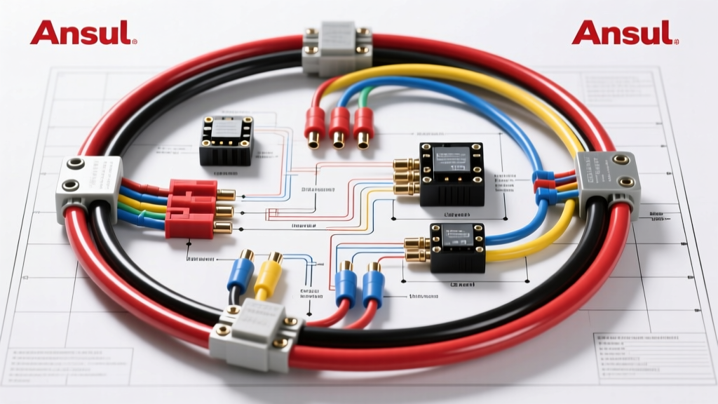
Complete Wiring Diagram for Ansul System Integration
Integrating a fire suppression system into heavy-duty off-highway vehicles, mining trucks, and forestry equipment requires precise electrical coordination between the suppression control head, the chassis Power Distribution Panel (PDP), and the engine Electronic Control Module (ECM). This complete wiring diagram for Ansul system integration focuses on the widely deployed Ansul LVS (Liquid Vehicle System) and Checkfire control architectures. Unlike standard passenger vehicles, heavy-duty platforms demand robust environmental sealing, high-current actuation circuits, and seamless J1939 CAN bus communication to trigger automated engine shutdown sequences during a thermal event.
Core Architecture of the Ansul Vehicle Suppression Circuit
The electrical backbone of an Ansul mobile suppression system relies on a dedicated control module that monitors thermal detectors, manual pull stations, and actuation solenoids. The system must remain armed even when the vehicle's main ignition switch is turned off, provided the master battery disconnect is engaged. Therefore, the primary power feed is routed directly from the battery isolator stud, bypassing the ignition relay to ensure continuous fire monitoring in the engine bay.
Power and Ground Distribution (AWG and Routing)
Main power and ground circuits for the Ansul control module require 12 AWG copper wire to minimize voltage drop over long chassis runs, particularly in articulated haulers or extended-frame mining trucks. The control module typically draws less than 2.0 amps in standby mode, but the actuation solenoid requires a momentary surge of up to 15 amps. Using undersized wire can result in a voltage drop below the solenoid's 9.0V DC threshold, leading to a failure to discharge. All primary power connections must utilize sealed ring terminals with heat-shrink adhesive liners to prevent moisture intrusion and subsequent galvanic corrosion.
Step-by-Step Wiring Diagram Walkthrough
1. Actuation and Detector Loop Wiring
The detection circuit utilizes a normally-closed (NC) series loop. In an Ansul LVS setup, this loop connects mechanical thermal fusible links or electrical thermal switches. If an electrical switch reaches its threshold (typically 300°F / 149°C), the internal contacts open, breaking the continuity of the detection loop. The control module instantly registers this open circuit as a fire event and triggers the discharge sequence. Wire colors for the detector loop are standardized in heavy-duty applications: Yellow (Signal In) and Yellow with a Black Tracer (Signal Out).
2. Engine Shutdown and J1939 CAN Bus Integration
Modern heavy-duty diesel engines no longer rely on simple hardwired fuel solenoid kill-switches. Instead, the Ansul control module integrates directly with the vehicle's SAE J1939 Controller Area Network (CAN). Upon detecting a fire, the Ansul module broadcasts a specific Suspect Parameter Number (SPN) message across the CAN High and CAN Low lines. The ECM receives this message, illuminates the dash Malfunction Indicator Lamp (MIL), and executes a controlled idle-down and shutdown sequence to prevent the engine cooling fan from fanning the flames. For detailed J1939 messaging protocols regarding auxiliary fire suppression, refer to the SAE J1939 standard documentation.
Heavy-Duty Connector and Pinout Specification Table
The primary interface between the Ansul control module and the chassis harness utilizes a 12-pin TE Connectivity DEUTSCH DTM series connector. This connector provides IP68-level environmental sealing, which is critical for vehicles subjected to high-pressure washdowns and severe dust ingress. For comprehensive connector cavity and wedge lock specifications, consult the TE Connectivity DEUTSCH DT/DTM technical catalog.
| Pin | Function | Wire Color | AWG Size | Termination Type |
|---|---|---|---|---|
| 1 | 12V+ Battery Constant (Master Disconnect) | Red | 12 AWG | Sealed Ring Terminal |
| 2 | Chassis Ground | Black | 12 AWG | Sealed Ring Terminal |
| 3 | Ignition Switched 12V (System Arming) | White | 16 AWG | DEUTSCH Socket |
| 4 | J1939 CAN High (ECM Shutdown Request) | Green | 20 AWG Shielded | DEUTSCH Socket |
| 5 | J1939 CAN Low (ECM Shutdown Request) | Yellow | 20 AWG Shielded | DEUTSCH Socket |
| 6 | Agent Discharge Solenoid + | Orange | 14 AWG | DEUTSCH Socket |
| 7 | Agent Discharge Solenoid - | Brown | 14 AWG | DEUTSCH Socket |
| 8 | Telematics / MDM Alarm Input (Active Low) | Purple | 18 AWG | DEUTSCH Socket |
| 9 | Detection Loop In (NC Series) | Blue | 18 AWG | DEUTSCH Socket |
| 10 | Detection Loop Out (NC Series) | Blue/Black | 18 AWG | DEUTSCH Socket |
| 11 | Manual Pull Station Loop | Gray | 18 AWG | DEUTSCH Socket |
| 12 | Auxiliary Relay Output (HVAC Shutoff) | Tan | 16 AWG | DEUTSCH Socket |
Wire Routing and Environmental Protection Standards
Routing the wiring harness for an Ansul system requires strict adherence to thermal and mechanical clearance guidelines. According to NFPA 17A guidelines for mobile and industrial extinguishing systems, all wiring must be secured a minimum of 18 inches away from exhaust manifolds, turbochargers, and DPF (Diesel Particulate Filter) regeneration zones. Where this clearance cannot be achieved due to the compact nature of modern engine bays, the wiring must be encased in high-temperature fiberglass sleeving or corrugated nylon loom rated for continuous 150°C exposure. Furthermore, harnesses must be secured every 12 inches using UV-resistant, stainless-steel cushion clamps rather than standard plastic zip-ties, which become brittle and fail under high-vibration off-road conditions.
Common Failure Modes and Multimeter Diagnostics
When troubleshooting an Ansul suppression system that fails to arm or discharge, technicians must move beyond simple visual inspections and utilize a digital multimeter (DMM) to perform voltage drop and resistance tests.
Voltage Drop Across the Actuation Solenoid
A common failure mode occurs when the control module registers a fire event and attempts to fire the actuation solenoid, but the solenoid fails to pull the mechanical puncture pin. This is rarely a faulty solenoid; it is almost always a voltage drop issue caused by corroded inline fuses or poor chassis grounds.
- Step 1: Disconnect the solenoid connector and set your DMM to measure DC Voltage.
- Step 2: Initiate a manual test discharge from the control head.
- Step 3: Measure the voltage at the harness side of the solenoid connector (Pins 6 and 7). You must read a minimum of 10.5V DC during the 3-second discharge window.
- Step 4: If voltage reads below 9.0V, perform a voltage drop test on the ground circuit (Pin 7 to battery negative) to identify hidden resistance.
Solenoid Coil Resistance Verification
Before replacing a suspected faulty actuation cartridge, verify the internal coil resistance. Disconnect the cartridge from the harness and measure across the two solenoid pins. A healthy Ansul LVS electrical actuation solenoid will typically measure between 2.5Ω and 4.0Ω at room temperature. An infinite reading (OL) indicates a broken internal coil wire, while a reading below 1.0Ω indicates a short circuit that will blow the control module's internal protection fuse.
False Alarms from Chassis Ground Loops
Intermittent false fire alarms are frequently traced back to ground loop interference or failing thermal switches. If the detection loop (Pins 9 and 10) shows fluctuating resistance rather than a solid 0.0Ω (closed circuit), moisture has likely compromised one of the inline thermal switches. Dielectric grease must be applied to all spade connections on mechanical thermal links to prevent oxidation, which artificially increases circuit resistance and tricks the control module into reading an open-circuit fault.