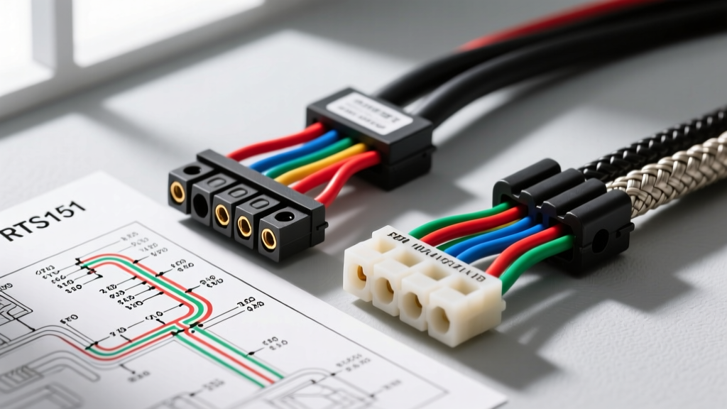
The Critical Role of the RTS151 in Electronic Power Steering
The transition from hydraulic racks to Electronic Power Steering (EPS) has fundamentally changed steering diagnostics. At the heart of this system is the RTS151 (Rotary Torque Sensor 151), a precision component that measures driver steering input and communicates torque demands to the EPS control module. Because the RTS151 operates in a high-vibration, high-heat environment near the steering rack and exhaust components, its wiring harness is a frequent point of failure. Understanding the rts151 wiring diagram is not just about knowing which wire goes where; it is about understanding signal integrity, electromagnetic interference (EMI) shielding, and the critical differences between replacement harness options.
When a vehicle presents with stiff steering, a flashing EPS warning lamp, or diagnostic trouble codes like C056E (Steering Angle Sensor Circuit) or U0126 (Lost Communication with Steering Angle Sensor Module), the wiring pigtail is often the true culprit. This guide breaks down the exact RTS151 pinout, compares OEM versus aftermarket replacement harnesses, and provides expert-level diagnostic strategies for automotive electrical technicians.
Complete RTS151 Wiring Diagram and Pinout Configuration
The RTS151 utilizes a 6-way sealed connector (typically a TE Connectivity AMP Superseal 1.5 series) to interface with the EPS module. The circuit relies on a 5-volt reference, a dedicated ground, two inverse analog torque signals for redundancy, and a high-speed CAN bus pair for module communication. Below is the definitive pinout reference for the RTS151 sensor harness.
| Pin | Circuit Function | Wire Color (OEM Std) | AWG Size | Wire Type / Shielding |
|---|---|---|---|---|
| 1 | 5V Reference (VREF) | Red | 20 AWG | Cross-Linked (XLPE) |
| 2 | Torque Signal A (Analog) | Green/White | 22 AWG | Foil Shielded + Drain |
| 3 | Torque Signal B (Analog) | Green/Black | 22 AWG | Foil Shielded + Drain |
| 4 | CAN-High (Network) | Yellow | 22 AWG | Twisted Pair (Unshielded) |
| 5 | CAN-Low (Network) | Purple | 22 AWG | Twisted Pair (Unshielded) |
| 6 | Sensor Ground (GND) | Black | 20 AWG | Cross-Linked (XLPE) |
Understanding the Redundant Analog Signals
Pins 2 and 3 carry the actual torque measurement data. To ensure safety and fault tolerance, the RTS151 outputs two inverse analog signals. As the driver turns the wheel, Signal A ramps from 0.5V to 4.5V, while Signal B simultaneously ramps from 4.5V down to 0.5V. The EPS module continuously adds these two voltages together; if the sum does not equal exactly 5.0V (±0.1V tolerance), the module immediately disables power assist to prevent runaway steering, triggering a fail-safe mode. According to the AA1Car Automotive Electrical Steering Guide, a variance of just 0.15V between the expected sum and the actual sum is enough to set a hard C056E code.
Product Selection Guide: OEM vs. Aftermarket RTS151 Pigtails
When the RTS151 pigtail is damaged by heat, chafing, or corrosion, selecting the right replacement harness is critical. The market is flooded with options, but they are not created equal. The EPS motor generates massive electromagnetic interference (EMI) due to the high-amperage 3-phase AC drive currents. If your replacement harness lacks proper shielding, the analog torque signals will absorb this noise, causing erratic steering assist.
| Feature | Tier 1: OEM Dealer Harness | Tier 2: Premium Aftermarket (e.g., SMP, Dorman) | Tier 3: Budget / White-Box (eBay/Amazon) |
|---|---|---|---|
| Insulation Material | XLPE (Cross-Linked Polyethylene) - Withstands 150°C | High-Temp PVC or Tefzel - Withstands 125°C | Standard PVC - Withstands 90°C (Melts near exhaust) |
| Signal Shielding | Aluminum Foil + Copper Braid with dedicated drain wire | Aluminum Foil Shield with drain wire | None (High risk of EMI noise faults) |
| Terminal Metallurgy | Gold-plated copper alloy (corrosion resistant) | Tin-plated copper alloy | Brass or nickel-plated (high resistance over time) |
| CAN Bus Twisting | Factory twisted at exact 1-inch pitch for impedance matching | Twisted, but pitch may vary slightly | Parallel wires (Causes CAN bus reflection errors) |
| Selection Verdict | Best for Dealerships & Warranty Work. Guaranteed fitment and longevity. | Best for Independent Shops. Excellent balance of price and OEM-level reliability. | Avoid at all costs. Will cause repeat comebacks and phantom EPS codes. |
Wire Gauge, Shielding, and Routing Specifications
When splicing a new RTS151 pigtail into the vehicle's main chassis harness, adhering to SAE J1939 and automotive wiring standards is mandatory. You cannot simply use standard 18 AWG primary wire from a bulk spool.
- Power and Ground (Pins 1 & 6): Must be 20 AWG. Using a smaller gauge will cause a voltage drop on the 5V reference circuit. A 0.2V drop on the VREF circuit will skew the entire torque signal scale, resulting in asymmetric steering assist (e.g., easier to turn left than right).
- Analog Signals (Pins 2 & 3): Must be 22 AWG shielded cable. When stripping the shielded wire, you must carefully fold back the aluminum foil and wrap the bare copper drain wire. The drain wire must be grounded at the EPS module connector backshell, not at the sensor side. Grounding both ends creates a ground loop, which will actually amplify EMI noise rather than block it.
- CAN Bus Pair (Pins 4 & 5): Must be 22 AWG and tightly twisted. The twisting is what provides Common Mode Rejection (CMR), allowing the CAN transceiver to ignore outside electrical noise. If you must splice the CAN wires, maintain the twist rate right up to the crimp barrel. Leave no more than 1 inch of untwisted wire at the termination point.
Real-World Troubleshooting: RTS151 Circuit Failure Modes
Before cutting and splicing a new harness based on the rts151 wiring diagram, verify the failure mode. The Haynes Automotive Repair Tutorials emphasize that visual inspection and oscilloscope testing should always precede invasive repairs.
Symptom-Cause-Fix Decision Tree
Symptom 1: EPS Light ON, DTC U0126 (Lost Comm with SAS)
- Cause: CAN-High or CAN-Low circuit open, shorted to ground, or shorted together. Often caused by the harness rubbing against the steering column intermediate shaft U-joint.
- Fix: Check CAN bus termination resistance (should be 60 ohms across Pins 4 and 5 with the battery disconnected). If resistance is 120 ohms, you have an open circuit in the RTS151 CAN pigtail. Splice in a premium Tier 2 harness.
Symptom 2: Erratic Steering Assist, DTC C056E (Torque Sensor Circuit)
- Cause: EMI interference on Signal A or Signal B due to missing shielding, or a high-resistance ground on Pin 6.
- Fix: Connect a PicoScope to Pins 2 and 3. Turn the steering wheel slowly. If the voltage waveforms show high-frequency 'fuzz' or spikes exceeding 200mV of noise, the shield drain wire is compromised or missing. Replace the harness with a fully shielded OEM or Tier 2 unit.
Symptom 3: Asymmetric Steering Effort (Pulls or heavy in one direction)
- Cause: Voltage drop on the 5V Reference (Pin 1) or Sensor Ground (Pin 6). The EPS module calculates center-point based on a perfect 2.5V baseline. A voltage drop shifts this baseline.
- Fix: Perform a voltage drop test across Pin 1 and Pin 6 with the key ON, engine OFF. Any reading above 0.05V indicates corroded terminals or undersized replacement wire. Re-crimp using the correct TE Connectivity 58431-1 ratcheting crimp tool to ensure proper terminal compression.
Best Practices for Connector Replacement and Sensor Calibration
If you are replacing the RTS151 sensor itself alongside the harness, pay strict attention to mechanical torque specs and software calibration. The RTS151 mounting bolts to the steering rack pinion must be torqued to exactly 12 Nm. Over-torquing can bind the internal rotary potentiometer, causing a physical hard spot in the steering.
Furthermore, once the new harness and sensor are installed, the EPS module must undergo a Steering Angle Sensor (SAS) Center Point Calibration via a bi-directional scan tool. This calibration teaches the module the exact 2.5V baseline of the new sensor. Skipping this step will result in the steering wheel being off-center, even if the wiring diagram was followed perfectly. Always use dielectric grease (such as Nyogel 760G) on the RTS151 connector cavity before mating it to prevent galvanic corrosion between the gold-plated sensor pins and the tin-plated harness terminals.