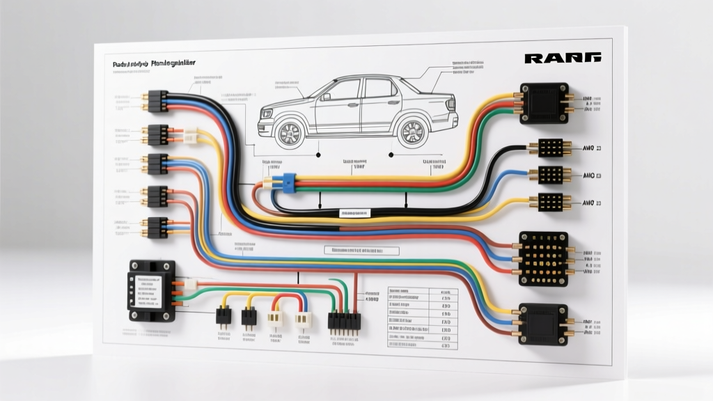
Navigating the Ram Body Builder Wiring Diagram Ecosystem
For commercial upfitters, fleet technicians, and serious DIYers, the Ram body builder wiring diagram portal is the definitive blueprint for modifying Heavy Duty (2500/3500) platforms. Unlike standard consumer service manuals, body builder guides focus on auxiliary power distribution, Power Take-Off (PTO) integration, and multiplexed lighting networks. Modern Ram trucks (2019+ current generation) rely heavily on the Body Control Module (BCM) and Local Interconnect Network (LIN) buses to manage electrical loads. Hard-splicing into factory harnesses without consulting these specific schematics almost guarantees CAN bus faults, voltage drops, and voided warranties.
In this complete walkthrough, we will decode the critical sections of the Ram body builder schematics, focusing on auxiliary switch routing, PCM-driven PTO controls, and the strict grounding protocols required by the Intelligent Battery Sensor (IBS) system.
Auxiliary Upfitter Switch Walkthrough: Overhead Console to Relay Block
The 2019+ Ram 2500 and 3500 models feature an overhead console with six auxiliary switches. Reading the body builder diagram for this circuit reveals that these switches do not carry the primary load current. Instead, they send a low-current logic signal via a LIN bus to the BCM. The BCM then triggers a dedicated auxiliary relay block located behind the front grille/bumper assembly.
When routing wires from the factory blunt-cut pigtails to your aftermarket equipment (e.g., winch solenoids, LED light bars, or beacon strobes), you must adhere to the AWG and circuit protection limits outlined in the schematic. Switches 1 through 4 are rated for 30 amps, while Switches 5 and 6 are rated for 40 amps. The factory output wires are typically 10 AWG and 8 AWG, respectively, terminated in weather-sealed Metri-Pack 280 connectors.
Table: Upfitter Switch Circuit Specifications & Wire Colors
| Switch ID | Max Amperage | Wire Gauge (AWG) | OEM Wire Color Code | Recommended Fuse/Breaker |
|---|---|---|---|---|
| Aux 1 | 30A | 10 AWG | RD/WT (Red/White) | 25A MaxiFuse |
| Aux 2 | 30A | 10 AWG | RD/GY (Red/Gray) | 25A MaxiFuse |
| Aux 3 | 30A | 10 AWG | RD/LB (Red/Light Blue) | 25A MaxiFuse |
| Aux 4 | 30A | 10 AWG | RD/TN (Red/Tan) | 25A MaxiFuse |
| Aux 5 | 40A | 8 AWG | RD/YL (Red/Yellow) | 35A MaxiFuse |
| Aux 6 | 40A | 8 AWG | RD/VT (Red/Violet) | 35A MaxiFuse |
Note: Always use OEM Mopar pigtail harnesses (e.g., part number 05017479AA) to interface with the auxiliary relay block. Using T-taps or piercing probes on Ram LIN bus wires will introduce micro-corrosion and resistance, leading to U0140 (Lost Communication with BCM) diagnostic trouble codes.
Power Take-Off (PTO) and High-Idle PCM Integration
Integrating hydraulic pumps, dump beds, or aerial lifts requires interfacing with the 6.7L Cummins Engine Control Module (ECM). The Ram body builder wiring diagram explicitly warns against probing the ECM connectors (C1 Black, C2 Gray, C3 Green) directly with aftermarket wires. Instead, Mopar provides an inline PTO prep harness that plugs between the factory ECM connectors and the engine harness.
The PTO circuit requires three primary signals: PTO Request, PTO Set/Resume (for RPM control), and a ground reference. Furthermore, the High-Idle feature must be enabled via the ECM to maintain alternator output and hydraulic pressure when the vehicle is stationary. According to Ram Body Builder Portal documentation, the ECM monitors engine oil temperature, coolant temperature, and brake pedal position before allowing PTO engagement.
Table: 6.7L Cummins PTO & High-Idle Inline Harness Pinouts
| Function | Circuit Designation | Wire Color | Signal Type | Operational Requirement |
|---|---|---|---|---|
| PTO Request | K90 | DB/YL (Dark Blue/Yellow) | 12V Active High | Ignition ON, Park Brake Set |
| PTO Set/Resume | K92 | TN/OR (Tan/Orange) | Momentary 12V | Used to step RPM up/down |
| High Idle Request | K15 | WT/PK (White/Pink) | Ground Trigger | Overrides base idle to ~1200 RPM |
| PTO Output (Feedback) | K95 | GY/RD (Gray/Red) | 12V Output | Energizes hydraulic solenoid relay |
The Intelligent Battery Sensor (IBS) and Strict Grounding Rules
One of the most frequently misunderstood sections of the Ram body builder guide involves the dual-battery 6.7L Cummins setup and the Intelligent Battery Sensor (IBS). The IBS is a shunt-style sensor mounted directly on the negative battery terminal of the primary (passenger side) battery. It measures voltage, current, and temperature to calculate the State of Charge (SOC) and State of Health (SOH), sending this data to the BCM via LIN bus to regulate the smart alternator.
Critical Upfit Rule: Never attach auxiliary ground wires directly to the negative battery post. If you bypass the IBS shunt, the BCM will receive inaccurate current draw data. This typically results in the BCM commanding the alternator to reduce output, leading to chronic undercharging, battery sulfation, and eventual failure of the starting system. All heavy-duty auxiliary grounds (e.g., winch grounds, inverter grounds) must be terminated at the designated chassis ground studs (such as G104 on the left frame rail) or the dedicated engine block ground pad, using a minimum of 4 AWG wire and a torque of 18 Nm (13 lb-ft).
Snowplow Prep and Frontal Lighting Isolation
For trucks equipped with the Snowplow Prep Package (Sales Code ACA), the body builder diagrams detail a complex headlamp isolation relay network. Because modern Ram LED and projector halogen headlamps use Pulse Width Modulation (PWM) for daytime running lights (DRL) and feature strict CAN bus current monitoring, adding high-draw plow lights directly to the headlight circuit will trigger a BCM shutdown.
The isolation diagram shows a dedicated 30A ISO relay triggered by the BCM via a DG/OR (Dark Green/Orange) wire. When the plow joystick is engaged, the BCM cuts power to the factory headlamps and energizes the isolation relay, sending dedicated B+ power from the front PDC to the plow harness. Upfitters must use Mopar Wiring Repair approved Deutsch DT connectors for the plow-side harness to ensure IP67 waterproofing and prevent salt-induced galvanic corrosion.
Common Upfit Failure Modes and Troubleshooting
When troubleshooting an aftermarket upfit on a modern Ram, always cross-reference your physical wiring against the body builder schematics. Here are common failure modes:
- Symptom: Auxiliary switches work for 3 seconds, then click off.
Cause: The BCM detects an inrush current spike exceeding the programmed threshold for that specific switch circuit.
Fix: Install a soft-start relay or a PWM dimmer module for LED light bars to reduce capacitive inrush current. - Symptom: U0140 or U0001 CAN bus codes after installing a trailer brake controller or lighting module.
Cause: Splicing into the trailer lighting module (TIM) multiplexed wires instead of using the dedicated blunt-cut trailer interface wires.
Fix: Remove T-taps, solder and heat-shrink all splices, and ensure the shield drain wire on the CAN-C bus is properly grounded. - Symptom: Alternator whining or voltage fluctuation when PTO is active.
Cause: Auxiliary load grounds are tied to the engine block without proper surface preparation, creating a floating ground that interferes with the ECM's 5V reference sensors.
Fix: Sand the ground pad to bare metal, apply dielectric grease after torquing, and verify voltage drop across the ground cable is less than 0.1V under load.
For comprehensive EMC (Electromagnetic Compatibility) guidelines regarding aftermarket relays and solenoids on commercial vehicles, refer to the SAE J1113 Standards. Ensuring your upfit complies with these standards prevents radio frequency interference (RFI) from disrupting the Ram's Uconnect, GPS, and tire pressure monitoring systems.