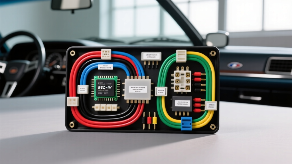
Introduction to the Fox Body EEC-IV Architecture
The Fox Body platform, specifically the 1987 through 1993 5.0L V8 models, relies on the Ford EEC-IV (Electronic Engine Control, 4th Generation) system. When diagnosing drivability issues, performing an engine swap, or tracing a parasitic draw, accessing an accurate 87 93 mustang wiring diagram is critical. Unlike modern CAN-bus multiplexed systems, the EEC-IV utilizes a dedicated 60-pin PCM connector with discrete, hardwired analog and digital circuits. This advanced technical deep dive explores the OEM wire color codes, AWG specifications, connector types, and common failure points inherent to the Fox Body engine harness.
Whether you are working with a 1987-1988 Speed Density system or a 1989-1993 Mass Air Flow (MAF) setup, the foundational EEC-IV 60-pin architecture remains remarkably consistent. The PCM is typically located in the passenger side kick panel, utilizing an Amp Multi-Match 60-pin connector. Understanding the specific pinouts, sensor reference voltages, and dedicated grounding strategies is essential for proper diagnosis and harness fabrication.
EEC-IV 60-Pin PCM Connector Pinout Matrix
The following table details critical pins on the 60-way EEC-IV connector. Wire colors listed are based on OEM Ford Motorcraft specifications for the 5.0L HO V8. Always verify with a digital multimeter (DMM), as previous owners may have altered harnesses.
| Pin | Function | OEM Wire Color | AWG / Spec |
|---|---|---|---|
| 1 | VREF (5-Volt Reference) | Light Green/Orange Stripe | 20 AWG |
| 2 | ECT (Engine Coolant Temp) | Dark Green/Light Green | 20 AWG |
| 4 | CID (Cylinder ID Sensor) | Dark Blue/White Stripe | 20 AWG |
| 12 | MAF Signal (89-93 Models) | Light Blue/Red Stripe | 18 AWG |
| 22 | Injector 1 Control | Light Blue/Orange Stripe | 18 AWG |
| 27 | HEGO Ground (Dedicated) | Black/White Stripe | 18 AWG |
| 37 | SPOUT (Ignition Timing) | White/Light Blue Stripe | 20 AWG |
| 49 | HEGO Dedicated Ground | Black/White Stripe | 18 AWG |
| 56 | VREF Return (Signal RTN) | Gray/Red Stripe | 20 AWG |
| 60 | Power Ground (PCM Case) | Black/White Stripe | 12 AWG |
According to SAE J1128 standards for low-tension primary cable, the 18-20 AWG wires used for sensor signals are designed to minimize voltage drop over the relatively short distances of the engine bay, while the 12 AWG grounds handle the bulk current return for the PCM's internal drivers.
TFI-IV Ignition System and SPOUT Circuit Analysis
The Thick Film Ignition (TFI) module is a frequent failure point on the 87-93 Mustang. Mounted directly on the distributor, the TFI module relies on the stator to generate the Profile Ignition Pickup (PIP) signal. The PIP signal (Gray wire) is sent to Pin 56 on the EEC-IV PCM, which then calculates the required dwell and timing advance.
The PCM sends the computed timing back to the TFI module via the SPOUT (Spout Output) circuit on Pin 37 (White/Light Blue wire). When diagnosing a no-spark condition or erratic timing, technicians must test the SPOUT circuit. If the SPOUT connector (the small inline plug near the distributor) is removed, the TFI module defaults to a base timing of 10 degrees BTDC. If the vehicle runs with the SPOUT unplugged but dies or backfires when plugged in, the fault lies in the PCM's internal timing driver or a short in the White/Light Blue wire.
Pro-Tip: Heat soak is the primary killer of the TFI module. When replacing it, always apply a generous layer of dielectric heat-sink compound between the module and the distributor base. Never install a TFI module dry.
HEGO Sensor Circuit and the Ground Loop Dilemma
The 1987-1993 5.0L Mustangs utilize narrowband Heated Exhaust Gas Oxygen (HEGO) sensors. A common mistake when reading a generic 87 93 mustang wiring diagram is assuming the O2 sensor grounds through the engine block or exhaust pipe. Ford specifically engineered a dedicated HEGO ground circuit to prevent ground loop interference.
On the widely used A9L (5-speed) and A9P (automatic) PCM calibrations, Pin 49 serves as the dedicated HEGO ground (Black/White wire). This wire routes directly from the PCM to the O2 sensor harness. If a technician splices the O2 sensor ground to the chassis or engine block, the PCM will read a voltage offset caused by the potential difference between the block and the PCM case. This results in a false lean or rich condition, causing the fuel trims to skew wildly and resulting in poor drivability or failed emissions.
When testing the HEGO signal (Dark Green/Orange wire on Pin 29), a healthy sensor should oscillate between 0.1V (lean) and 0.9V (rich) at a frequency of roughly 1Hz at operating temperature. If the signal is pegged at 0.0V, check the dedicated ground on Pin 49 for continuity back to the PCM.
Charging System Vulnerabilities: The 1G to 3G Alternator Swap
No technical discussion of the Fox Body wiring harness is complete without addressing the factory charging circuit. The 1987-1993 Mustangs came equipped with a 1G or 2G style alternator, utilizing a 10 AWG Black/Orange main power wire routed through a fusible link to the starter solenoid. This factory wiring is a notorious fire hazard, especially when owners install high-draw electric fans, fuel pumps, or aftermarket audio systems.
Upgrading to the later Ford 3G 130-Amp alternator (commonly pulled from a 1990s Ford Taurus or F-150) is a mandatory safety and performance modification. This requires bypassing the factory 10 AWG harness.
3G Alternator Wiring Specifications
- Main B+ Output: Use 4 AWG high-strand-count welding cable routed directly from the alternator B+ post to the battery positive terminal.
- Overcurrent Protection: Install a 175A Mega Fuse within 18 inches of the battery positive terminal on the new 4 AWG wire.
- 3-Pin Regulator Connector:
- Pin 1 (Stator): Not utilized on the internally regulated 3G. Leave disconnected or cap off.
- Pin 2 (Light/I): Connect to the Yellow/Light Blue wire from the factory dash charge indicator lamp.
- Pin 3 (Sense/A): Connect to the Orange/Light Blue wire, which must be routed to a clean 12V switched source or directly to the B+ post to ensure accurate voltage regulation.
For comprehensive wiring schematics regarding Ford charging systems, Ford Fuel Injection provides excellent reference materials on the evolution of Ford's electrical architecture.
Internal EEC-IV PCB Failure Modes
Even if the external 87 93 mustang wiring diagram is perfectly intact, the EEC-IV PCM itself is prone to age-related internal failures. The A9L and A9P computers contain three electrolytic capacitors on the main printed circuit board. Over decades of heat cycling, these capacitors leak a highly corrosive electrolyte fluid.
This fluid eats through the copper traces on the PCB. The most commonly destroyed trace is the one leading to Pin 22 (Injector 1) or Pin 58 (Fuel Pump Relay). Symptoms of capacitor leakage include a single dead cylinder (misfire on cylinder 1) that shows a perfect injector pulse on a noid light but no actual fuel delivery due to a broken trace, or a crank-no-start condition where the fuel pump primes but does not run during cranking. If diagnosing a Fox Body with unexplained injector or fuel pump issues, visually inspecting the EEC-IV PCB for blue/green corrosion is a mandatory diagnostic step.
Authoritative References
For further technical validation and factory service manual (FSM) cross-referencing, consult the following resources: