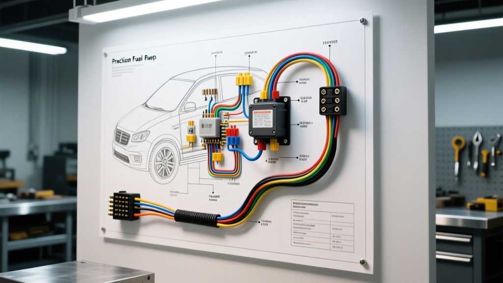
Introduction to Precision Fuel Pump Electrical Architecture
When replacing a failing fuel delivery system, consulting the correct Precision Fuel Pumps wiring diagram is the difference between a permanent fix and a recurring diagnostic nightmare. Precision Fuel Pumps, widely recognized for their OE-replacement and high-performance modules, rely on precise electrical parameters to maintain optimal fuel pressure and volume. A slight deviation in voltage, an undersized ground wire, or a corroded terminal will cause the pump armature to draw excess amperage, leading to commutator arcing, internal cavitation, and premature failure.
This complete wiring diagram walkthrough breaks down the electrical topology of standard and pulse-width modulated (PWM) fuel pump circuits. Whether you are installing a direct-fit drop-in module or wiring a high-flow external pump for forced induction applications, understanding the relay paths, wire gauges, and connector pinouts is mandatory for a reliable repair.
Decoding the Standard 3-Pin and 4-Pin Wiring Diagrams
The vast majority of legacy and standard-return fuel systems utilize a 3-pin or 4-pin electrical connector at the top of the fuel sender assembly. These connectors are typically Delphi Metri-Pack 150 or 280 series sealed housings. The wiring diagram for these systems is straightforward but requires strict adherence to wire color codes and gauge specifications to prevent voltage drop.
OEM Pigtail and Harness Adapter Pinout Matrix
When splicing a new Precision Fuel Pumps pigtail into a factory harness, or when using an OE-adapted harness, reference the matrix below. This chart maps the standard functions, typical OEM wire colors for major domestic manufacturers, and the minimum required American Wire Gauge (AWG) to safely carry the inductive load of the pump motor.
| Pin | Function | GM Wire Color | Ford Wire Color | Chrysler Wire Color | Min AWG |
|---|---|---|---|---|---|
| A / 1 | Pump Power (+12V) | Grey | Pink / Black | Dark Green / White | 14 AWG (Std) / 12 AWG (High-Flow) |
| B / 2 | Pump Ground | Black | Black / Yellow | Black / Light Blue | 14 AWG (Std) / 12 AWG (High-Flow) |
| C / 3 | Fuel Level Sender | Purple | Yellow / White | Dark Green / Orange | 18 AWG |
| D / 4 | Low Fuel Warning | Tan / White | Black / Pink | Yellow / White | 18 AWG |
Note: Always verify pin positions using the mating connector diagram, as physical pin layouts can vary by specific vehicle model year and platform.
The Fuel Pump Relay Circuit: Power and Ground Paths
A common failure point in fuel delivery is not the pump itself, but the relay circuit that feeds it. The factory wiring diagram routes power from the battery through a main fuse block to the fuel pump relay. In a standard ISO mini-relay setup, the circuit operates as follows:
- Pin 30 (Power In): Receives constant battery voltage (B+) from a 15A or 20A fuse.
- Pin 85 (Coil Ground): Grounded by the Engine Control Module (ECM) or Powertrain Control Module (PCM) when the ignition is in the RUN or START position.
- Pin 86 (Coil Power): Receives switched 12V from the ignition circuit or ECM driver.
- Pin 87 (Switched Power Out): Feeds the fuel pump power wire (e.g., the Grey wire on GM applications).
Ford applications often include an Inertia Cutoff Switch (ICS) in the wiring diagram between the relay Pin 87 and the fuel pump. If the vehicle experiences a sudden deceleration or impact, the inertia switch breaks the circuit. When diagnosing a no-start condition after installing a new Precision pump, always verify continuity through the inertia switch before condemning the pump or relay.
Modern PWM Systems and the Fuel Pump Control Module (FPCM)
Late-model vehicles, particularly GM trucks (Silverado/Sierra) and modern Chrysler platforms, have abandoned the standard relay-and-resistor setup in favor of a Fuel Pump Flow Control Module (FPFCM) or Fuel Pump Control Module (FPCM). These systems use Pulse-Width Modulation (PWM) to vary the voltage supplied to the pump, typically ranging from 6V at idle to 12V under wide-open throttle (WOT).
PWM Wiring Diagram Walkthrough
The wiring diagram for a PWM system features a dedicated control module usually mounted on the frame rail. The module receives a 5V or 12V square-wave signal from the ECM via a dedicated CAN bus or low-speed serial data line. Warning: You cannot use a standard heavy-duty relay bypass harness on a PWM system. Supplying a constant 14.4V alternator output to a PWM-designed Precision Fuel Pump will cause the internal pressure relief valve to bypass continuously, overheat the fuel, and destroy the pump commutator within a few hundred miles.
When diagnosing PWM circuits, a standard digital multimeter (DMM) will show an 'averaged' voltage (e.g., 7.5V). To properly read the wiring diagram signals and verify the square wave duty cycle, an automotive oscilloscope is required. The ground side of the pump in these systems is often isolated and routed back through the FPCM, meaning the pump housing itself is not grounded to the chassis.
Upgrading to a Heavy-Duty Relay Harness for High-Flow Applications
If you are installing a high-flow Precision Fuel Pump (such as their 255 lph, 340 lph, or E85-compatible models) into an older vehicle, the factory 16 AWG or 18 AWG wiring is mathematically insufficient. High-flow pumps draw between 12 and 18 amps under peak pressure. Running 18 amps through 18-gauge wire and 20-year-old OEM connectors will result in severe voltage drop, starving the pump of the voltage it needs to maintain base fuel pressure.
Heavy-Duty Bypass Harness Specifications
To properly wire a high-flow pump, construct or purchase a heavy-duty bypass harness that adheres to the following specifications:
- Wire Gauge: 10 AWG XLPE (Cross-Linked Polyethylene) or GXL automotive primary wire for both power and ground runs.
- Relay: 40A or 50A sealed automotive relay (Bosch-style or equivalent Weather-Pack sealed relay).
- Overcurrent Protection: 30A MAXI fuse or 40A MIDI fuse located within 18 inches of the battery positive terminal.
- Trigger Source: Tap into the OEM fuel pump relay Pin 87 output to trigger the new heavy-duty relay Pin 85/86 coil. This ensures the new pump still shuts off during a collision or when the engine stalls.
Diagnosing Voltage Drop and Grounding Failures
According to SAE International standard J1128, voltage drop in a low-tension primary automotive circuit should not exceed 0.1V per connection or 0.2V for the entire length of the wire. A Precision Fuel Pump requires a minimum of 12.0V at the pigtail to achieve its rated flow volume. If your multimeter reads 10.5V at the pump while the engine is cranking, the pump will cavitate, and the engine will starve for fuel.
Step-by-Step Multimeter Testing Protocol
- Battery Baseline: Set your DMM to DC Volts. Measure directly across the battery posts with the key in the RUN position (fuel pump priming). Note the voltage (e.g., 12.6V).
- Positive Side Drop: Place the red DMM lead on the battery positive post and the black lead on the power pin of the fuel pump pigtail (back-probed). Have an assistant turn the key to RUN. The reading should be less than 0.3V. If it is higher, you have corrosion in the fuse block, relay, or inertia switch.
- Ground Side Drop: Place the black DMM lead on the battery negative post and the red lead on the ground pin of the fuel pump pigtail. Turn the key to RUN. The reading should be less than 0.1V. High readings here indicate a corroded chassis ground stud.
For ground stud repairs, always remove the factory ring terminal, clean the unibody or frame contact patch down to bare metal using a wire wheel, apply a thin layer of dielectric grease to prevent future oxidation, and torque the M6 or M8 ground bolt to the manufacturer specification (typically 89 to 106 in-lbs).
Terminal Crimping and Connector Sealing Standards
When repairing a damaged Precision Fuel Pumps pigtail, soldering is strictly prohibited in high-vibration, high-heat environments like a fuel tank module. Solder wicks moisture, creates a rigid point that snaps under vibration, and melts under high amperage loads. Instead, use an open-barrel crimp tool designed for Delphi Metri-Pack or Weather-Pack terminals. Always use the correct cavity plug or silicone weather seal to maintain the IP67 waterproof rating of the connector housing. For detailed terminal retention force and crimp height specifications, refer to the Delphi Technologies connector engineering catalogs.
Authoritative References & SAE Standards
Proper electrical integration of aftermarket and OE-replacement fuel components requires adherence to established automotive engineering standards. The wiring principles, AWG load capacities, and diagnostic voltage drop thresholds outlined in this walkthrough are derived from SAE J1128 Low Tension Primary Cable standards, OEM service documentation, and Precision Fuel Pumps official installation technical bulletins. Always consult the specific vehicle service manual for exact pinout variations, ECM driver logic, and model-specific ground locations before modifying any fuel delivery circuit.