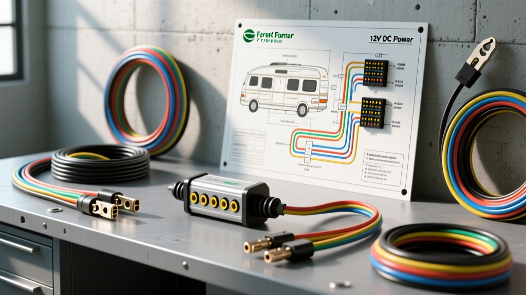
The Reality of Finding a Forest River Wiring Diagram PDF
Owners searching for a comprehensive Forest River wiring diagram PDF often hit a wall. Unlike passenger vehicles with standardized, chassis-specific factory service manuals, Forest River (and the broader RV industry) operates as a final-stage integrator. They build the living space and integrate third-party electrical systems. Consequently, a single, universal wiring schematic for a Forest River Cherokee, Salem, or Wildcat does not exist. Instead, the electrical architecture is divided into distinct sub-systems managed by specialized OEMs like WFCO, Progressive Dynamics, and Lippert Components (LCI).
To properly troubleshoot, upgrade, or repair your RV's electrical system, you must reference the component-level specifications and industry-standard routing protocols. This technical reference guide replaces the need for a generalized PDF by providing the exact wire color codes, AWG ratings, and pin configurations used in modern Forest River travel trailers and fifth wheels.
1. The 7-Way RV Blade Connector (Tow Vehicle Interface)
The umbilical cord connecting your tow vehicle to the Forest River trailer relies on the RVIA (Recreation Vehicle Industry Association) standard 7-way blade connector. Miswiring here is the leading cause of blown tow vehicle fuses and non-functional trailer brakes.
Standard RVIA 7-Way Pinout Specification
| Pin Position (Clock Face) | Function | Standard Wire Color | Minimum AWG Size | Forest River Routing Destination |
|---|---|---|---|---|
| 9 o'clock (Pin 1) | Left Turn / Stop | Yellow | 14 AWG | Tail light assembly (Driver side) |
| 10 o'clock (Pin 2) | Reverse / Backup Lights | Purple / Black | 14 AWG | Reverse lighting circuit / Surge brake lockout |
| 7 o'clock (Pin 3) | Ground (Chassis) | White | 10 AWG (or 8 AWG) | Trailer A-frame / Main chassis ground bus |
| 3 o'clock (Pin 4) | Right Turn / Stop | Green | 14 AWG | Tail light assembly (Passenger side) |
| 5 o'clock (Pin 5) | Electric Brakes | Blue | 12 AWG (or 10 AWG) | Dexter / Lippert electric brake assemblies |
| 1 o'clock (Pin 6) | 12V Auxiliary / Battery Charge | Red / Black | 10 AWG (or 6 AWG) | House battery bank via 30A/40A inline breaker |
| 11 o'clock (Pin 7) | Running / Tail / Marker Lights | Brown | 14 AWG | Clearance markers and tail light running circuit |
Expert Note: Forest River frequently uses a 10 AWG wire for the 12V Auxiliary (Pin 6) to support battery charging while towing. If upgrading to a large lithium house bank, upgrade this umbilical wire to 6 AWG and install a 50A DC-DC charger to prevent voltage drop over the 25-foot run.
2. Power Distribution Center (PDC) & Converter Wiring
The heart of the Forest River 12V DC and 120V AC house system is the Power Distribution Center (PDC). Most modern Forest River units utilize either a WFCO Technologies WF-8900 series or a Progressive Dynamics PD-4600 series power center.
WFCO 8955-PEC Power Center Specifications
- AC Input: 120V AC, 30A or 50A main breaker.
- DC Output: 12V DC, 55 Amp continuous.
- Main DC Output Wiring: 6 AWG stranded copper, routed from the converter's DC output lugs directly to the main 12V DC bus bar or fuse block.
- AC Branch Circuits: 12 AWG Romex for 20A breakers (microwave, GFCI receptacles); 14 AWG Romex for 15A breakers (lights, entertainment system).
- DC Branch Circuits: 12 AWG for 15A/20A blade fuses (water pump, awning, slide-outs); 14 AWG for 10A fuses (interior LED lighting).
Lead-Acid vs. Lithium Converter Wiring
If your Forest River RV came equipped with a standard WFCO 8955, it features a multi-stage charging profile designed for flooded lead-acid or AGM batteries. If you are upgrading to LiFePO4 (Lithium Iron Phosphate) batteries, the standard converter will not trigger the BMS (Battery Management System) properly and will undercharge the cells. You must replace the lower deck converter module with a dedicated Lithium profile unit (e.g., WFCO WF-9855-L or Progressive Dynamics PD-4655L). The physical wiring (6 AWG DC output) remains identical, but the voltage regulation curve changes from a 13.6V float to a strict 14.4V bulk/absorption phase.
3. Slide-Out and Leveling System Wiring (LCI)
Forest River integrates Lippert Components (LCI) for nearly all slide-out mechanisms and electric leveling jacks. These high-draw DC motors require heavy-gauge wiring and specialized solenoid relays.
Slide-Out Motor Wiring Protocol
- Power Source: Routed directly from the main 12V DC bus bar or house battery positive terminal, protected by a 30A or 40A Type II auto-reset circuit breaker.
- Wire Gauge: 10 AWG for short runs (under 10 feet); 8 AWG or 6 AWG for rear slide-outs or long cable runs to minimize voltage drop.
- Relay Pack: LCI uses a Trombetta-style directional solenoid pack. It requires four wires: two heavy-gauge motor leads (typically Black and Red) and two 14 AWG control wires connected to the interior momentary switch.
- Grounding: The motor casing and solenoid ground must be bonded to the trailer chassis using a minimum 10 AWG ring terminal, secured with a star washer to bite through powder coating or rust.
4. Breakaway Switch & Electric Brake Wiring
The breakaway system is a critical safety failsafe. If the trailer separates from the tow vehicle, the lanyard pulls a pin from the breakaway switch, sending full battery voltage directly to the electric brakes to lock the trailer axles.
Breakaway Circuit Routing
- Power In: 12 AWG Red wire from the positive terminal of the dedicated breakaway battery (or main house battery bank via a 20A inline fuse).
- Power Out: 12 AWG Black or Blue wire exiting the switch, spliced directly into the 7-Way Pin 5 (Blue Electric Brake wire).
- Common Failure Mode: Corrosion inside the breakaway switch housing causes high resistance. When the pin is pulled, voltage drops below 9V, failing to fully engage the brake magnets. Test this annually with a multimeter; you should read within 0.2V of your battery's resting voltage across the brake magnet wires when the pin is pulled.
5. Troubleshooting Decision Tree: 12V DC Power Loss
When interior 12V lights and the water pump fail simultaneously, follow this diagnostic path before ripping into walls looking for a severed wire:
- Check Shore Power / Battery Disconnect: Is the rotary battery disconnect switch in the 'USE' position? These switches control a high-amperage latching solenoid. If the solenoid fails, 12V power is cut to the PDC.
- Inspect the Main Inline Fuse: Locate the 30A or 50A main DC fuse located within 18 inches of the house battery positive terminal (per NEC and RVIA code). A blown main fuse kills the entire DC distribution panel.
- Verify PDC Reverse Polarity Fuses: On the WFCO or Progressive Dynamics PDC, locate the two 30A or 40A reverse polarity fuses on the DC distribution board. These blow if the battery cables are crossed during replacement. If these are blown, the converter will output 12V, but the branch circuits will remain dead.
- Test the Ground Bus: Using a multimeter, measure resistance between the PDC DC ground bus and the bare metal chassis. It should read less than 0.5 ohms. High resistance indicates a corroded main chassis ground strap.
Authoritative Reference Sources
Because Forest River does not publish a monolithic wiring PDF, technicians must rely on the OEM documentation for the integrated components. Always cross-reference your repairs with the following authorities:
- Recreation Vehicle Industry Association (RVIA) - For standard 7-way connector pinouts, low-voltage wire gauge requirements, and safety compliance codes.
- WFCO Technologies Technical Manuals - For Power Distribution Center schematics, converter charging profiles, and AC/DC bus routing.
- Lippert Components (LCI) Service Guides - For slide-out motor wiring, hydraulic pump solenoids, and electric leveling jack pinouts.
By treating your Forest River RV as a collection of specialized electrical sub-systems rather than a single vehicle, you can accurately trace faults, safely upgrade to lithium power, and maintain the integrity of your 12V and 120V networks without relying on a non-existent master diagram.