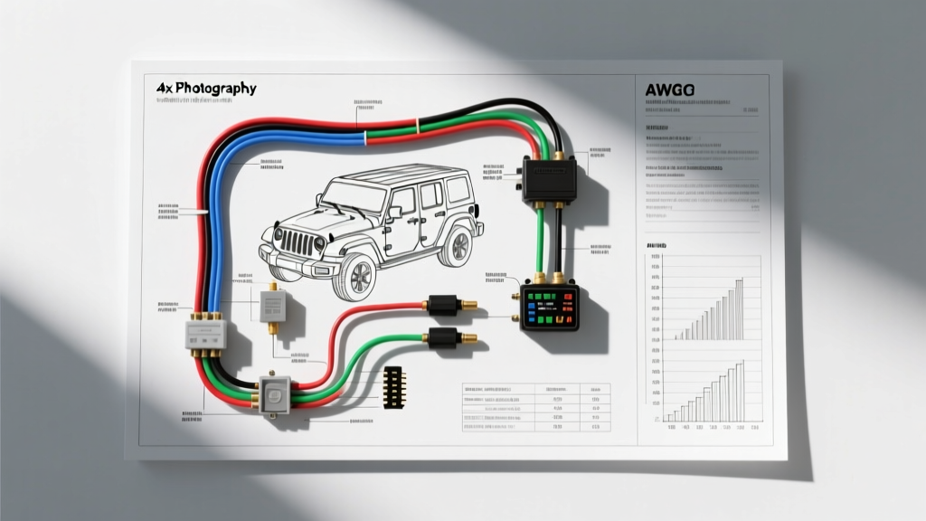
Transforming Your Onboard Air System: The Automatic Upgrade
For off-road enthusiasts and overlanders, an onboard air system is a mandatory modification. However, relying on a manual dashboard toggle switch to monitor and control your air compressor is not only inconvenient but potentially dangerous. Over-pressurizing your air tank or burning out a compressor motor due to thermal overload are common risks. Upgrading to an automated system requires a deep understanding of the wiring diagram of pressure switch integration, ensuring your 12V compressor activates only when tank pressure drops below a specific threshold and shuts off precisely at your target maximum PSI.
This guide details the complete electrical architecture for upgrading a standard 4x4 onboard air system (such as those found in Jeep Wranglers, Toyota Tacomas, and Ford Broncos) using a heavy-duty 12V air compressor, a Bosch-style ISO 7588 relay, and a normally-open (NO) automatic pressure switch. By moving the high-amperage load away from the dashboard and into the engine bay, you eliminate voltage drop, protect your vehicle's factory wiring harness, and introduce professional-grade automation.
Component Specifications and Wire Gauge Chart
Automotive electrical upgrades demand strict adherence to wire gauge sizing. Compressors are inductive loads that experience massive inrush currents (often 2x to 3x their running amperage) during startup. Sizing your wire based solely on the running amperage will result in severe voltage drop, melted insulation, and premature compressor failure. The following chart is based on SAE J1128 standards for high-temperature under-hood routing.
| Circuit Segment | AWG Size | Max Ampacity | Wire Color Code | Terminal Type |
|---|---|---|---|---|
| Battery (+) to Relay Pin 30 | 8 AWG | 50A | Red | 3/8" Ring Terminal (Adhesive Heat Shrink) |
| Relay Pin 87 to Compressor (+) | 8 AWG | 50A | Blue or Red | 1/4" Ring / Weather-Pack |
| Compressor Ground to Chassis | 8 AWG | 50A | Black | 3/8" Ring Terminal (Star Washer) |
| Relay Coil Ground (Pin 86) | 16 AWG | 10A | Black | 1/4" Spade or Ring |
| Pressure Switch to Relay Coil (Pin 85) | 16 AWG | 10A | Yellow | 1/4" Spade (Insulated Female) |
| Manual Override / Dash Switch | 16 AWG | 10A | White | Standard Blade Connector |
Step-by-Step: Wiring Diagram of Pressure Switch & Relay
To execute this upgrade, you must divide the circuit into two distinct halves: the High-Current Load Circuit and the Low-Current Control Circuit. The pressure switch acts as the bridge, utilizing a small electrical signal to command the heavy lifting of the relay.
1. The High-Current Load Circuit
Begin by mounting a 40A inline MAXI fuse within 8 inches of the vehicle's positive battery terminal. Run an 8 AWG red wire from the fuse to Pin 30 of your 5-pin Bosch-style relay. This is your constant 12V+ supply. Next, run an 8 AWG wire from Pin 87 (Normally Open contact) directly to the positive terminal of your air compressor. Pin 87a (Normally Closed) will remain unused in this specific configuration; tape it off or cut it flush to prevent accidental shorts.
Grounding is where most aftermarket compressor upgrades fail. Do not rely on the compressor's mounting bracket for a ground. Run a dedicated 8 AWG black wire from the compressor's negative terminal to a clean, bare-metal point on the chassis. Use a star washer to bite through the paint and apply dielectric grease over the terminal to prevent galvanic corrosion.
2. The Low-Current Control Circuit
This is where the core wiring diagram of pressure switch logic comes into play. Most aftermarket air switches (like the Viair 20005 or ARB models) are Normally Open (NO). This means the internal contacts remain separated until the manifold pressure drops below the cut-in threshold (typically 145 PSI), at which point the diaphragm forces the contacts closed.
Wire Pin 86 of the relay to a solid chassis ground using 16 AWG wire. Wire Pin 85 to one of the terminals on your pressure switch using 16 AWG yellow wire. The second terminal on the pressure switch will receive a switched 12V+ source. For a pure automatic setup, connect this to an ignition-switched fuse in your fuse box using an add-a-circuit tap. If you prefer a hybrid setup, route this wire to a heavy-duty manual toggle switch on your dashboard, allowing you to kill the automated system when the vehicle is parked.
Advanced Modification: Flyback Diode Integration
When studying advanced automotive schematics, you will notice a critical component often missing from basic kits: the flyback diode. Air compressors are highly inductive. When the pressure switch reaches the cut-out pressure (e.g., 200 PSI) and snaps open, the collapsing magnetic field inside the compressor motor generates a massive reverse voltage spike (inductive kickback). This spike can arc across the physical contacts inside your pressure switch, causing pitting, carbon buildup, and eventual welding of the contacts.
To protect your investment, solder a 1N5408 (3A, 1000V) flyback diode across the compressor's positive and negative terminals, or across the relay coil pins (85 and 86). If placing it at the compressor, the diode's cathode (the striped end) must point toward the positive 12V+ wire. This provides a safe recirculation path for the inductive spike, extending the lifespan of your pressure switch contacts by up to 400% according to Bosch automotive relay engineering guidelines.
Physical Installation and Pneumatic Sealing
Electrical perfection means nothing if the pneumatic trigger fails. The pressure switch typically features a 1/8" NPT (National Pipe Taper) male thread. When installing the switch into your aluminum air manifold or tank, never use standard Teflon tape. Shreds of PTFE tape can break off inside the manifold and lodge themselves inside the switch's diaphragm, causing it to stick open and run the compressor until thermal failure.
Instead, use a liquid pipe sealant rated for high-pressure air and vibration, such as Loctite 567 or a specialized pneumatic thread sealant. Torque the brass switch body to the manufacturer's specification (usually no more than 10-15 ft-lbs) to avoid cracking the internal Bakelite housing. Use an open-ended wrench to hold the manifold steady while tightening the switch to prevent twisting the entire air assembly.
Troubleshooting Common Pressure Switch Failures
Even with a perfect wiring diagram of pressure switch integration, environmental factors can cause issues. Use the following diagnostic tree to troubleshoot a compressor that refuses to shut off or fails to engage:
- Symptom: Compressor runs continuously past 200 PSI.
Cause: The internal contacts of the pressure switch have welded together due to inductive arcing, or the diaphragm is ruptured.
Fix: Disconnect the 12V+ wire from the switch. If the compressor continues to run, the relay is stuck closed. If it stops, replace the pressure switch and install a flyback diode. - Symptom: Compressor fails to engage when pressure drops below 145 PSI.
Cause: Voltage drop across the pressure switch terminals or a clogged pneumatic port.
Fix: Set your digital multimeter to DC Volts. Place the red probe on the 12V+ input terminal of the switch and the black probe on the output terminal while the system is calling for air. A reading higher than 0.2V indicates severe internal resistance or corrosion. Clean the spade connectors with contact cleaner or replace the switch. - Symptom: Compressor cycles rapidly (short-cycling).
Cause: Air leak in the check valve or manifold, causing pressure to drop instantly when the compressor shuts off.
Fix: Apply soapy water to the check valve and manifold fittings. Tighten or replace the leaking pneumatic component. The electrical circuit is functioning correctly.
References and Further Reading
For further validation of wire ampacity and inductive load management, refer to the following industry standards:
- SAE J1128: Low Tension Primary Cable - Society of Automotive Engineers guidelines for high-temperature wire insulation and ampacity derating in engine compartments.
- Viair Corporation Technical Manuals - Manufacturer specifications for duty cycles, inrush currents, and pneumatic switch thread sealing requirements.
- Bosch Automotive Relays and Switches - Engineering data on ISO 7588 relay pinouts, contact materials, and flyback diode integration for inductive loads.