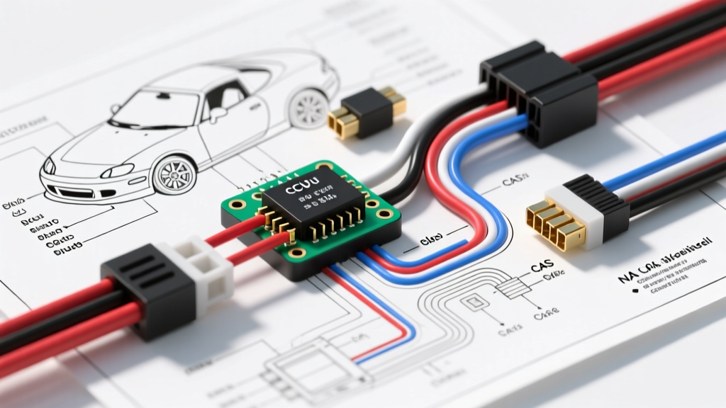
Comprehensive Guide to the NA Miata Wiring Diagram
The Mazda MX-5 Miata (NA generation, spanning the 1989 to 1997 model years) remains one of the most extensively modified and track-prepped sports cars in the world. Whether you are performing a modern engine swap, upgrading to a standalone engine management system, or simply diagnosing a 30-year-old electrical gremlin, mastering the NA Miata wiring diagram is mandatory. Unlike modern vehicles relying on complex CAN-bus networks, the NA platform utilizes a straightforward, predominantly analog multiplexed electrical architecture. This makes it highly accessible for DIY enthusiasts and professional fabricators alike, provided they understand Mazda's specific wire color codes, pinout configurations, and sensor signaling protocols.
Understanding the foundational architecture of the NA harness is critical. The main engine harness routes from the ECU (located behind the passenger side kick panel or under the seats depending on the exact year and left/right-hand drive configuration) through the firewall via a large multi-pin bulkhead connector. From there, it branches into the injector sub-harness, the ignition coil/distributor harness, and the sensor harness. Because these vehicles are now decades old, insulation breakdown, previous owner splice-jobs, and corrosion at the bulkhead connectors are the primary causes of electrical faults.
Main ECU Connector Pinout Specifications (1994-1997 1.8L)
The transition from the 1.6L B6 engine to the 1.8L BP engine in 1994 brought significant changes to the NA Miata wiring diagram. The 1.8L ECU features a larger connector footprint to accommodate additional emissions equipment, the Variable Intake Control System (VICS), and a heated oxygen sensor. Below is a reference table for the primary ECU connector pins on the 1994-1995 1.8L models, which are the most common candidates for track builds and OBD1 standalone conversions.
| Pin | Function | Wire Color | AWG / Notes |
|---|---|---|---|
| 1 | Main Ground (E1) | Black/Red | 18 AWG - Must have < 0.05V drop |
| 2 | Ignition 1 (IG1) | Black/Yellow | 16 AWG - Switched 12V from ignition |
| 3 | Main Relay Output | White/Red | 16 AWG - Constant 12V when relay engaged |
| 4 | Fuel Pump Control | Blue/Black | 18 AWG - ECU provides ground path |
| 5 | Tachometer Signal | Blue/White | 20 AWG - Pulses to instrument cluster |
| 6 | VICS Solenoid | Green/White | 18 AWG - Ground switched at ~5250 RPM |
| 7 | Idle Air Control (ISC) | Yellow/Blue | 18 AWG - Duty cycle controlled |
| 8 | Check Engine Light | Green/Red | 20 AWG - Ground switched for MIL |
| 9 | A/C Relay Cut | Blue/Red | 18 AWG - Disengages A/C at WOT |
| 10 | Diagnostic TEN | Green/White | 20 AWG - Jumper to GND for code reading |
1.6L vs 1.8L Harness Differences
When referencing a NA Miata wiring diagram, confusing the 1.6L and 1.8L harnesses is a common pitfall. The 1.6L (1989-1993) utilizes a hot-wire Mass Air Flow (MAF) sensor that outputs an analog 0-5V signal directly proportional to air mass. The 1.8L retains a similar MAF but introduces the VICS solenoid on the intake manifold, requiring an additional ground-switched circuit from the ECU. Furthermore, the 1.8L harness integrates a 4-wire heated oxygen sensor, whereas early 1.6L models used a simpler 1-wire or 3-wire unheated O2 sensor. Swapping a 1.8L engine into a 1.6L chassis requires either repinning the firewall bulkhead connector or splicing the 1.8L engine harness onto the 1.6L chassis harness, paying strict attention to the injector impedance differences (1.6L uses high-impedance, early 1.8L uses low-impedance requiring a resistor pack or ECU driver modification).
Crank Angle Sensor (CAS) & Ignition Wiring
The Crank Angle Sensor (CAS) is the heartbeat of the NA Miata's ignition and fuel injection timing. Housed entirely within the distributor assembly, the CAS generates both the Camshaft Position (CMP) and Crankshaft Position (CKP) signals using an internal optical pickup and a slotted timing disc. The NA Miata wiring diagram routes the CAS harness through a dedicated 4-pin connector.
- Pin 1 (12V Power): Black/White wire (18 AWG). Fed from the main relay. Must read battery voltage with the key in the 'ON' position.
- Pin 2 (Sensor Ground): Black/Red wire (18 AWG). Returns directly to the ECU logic ground, not the chassis ground.
- Pin 3 (CMP Signal): Blue/White wire (20 AWG). Outputs a 5V square wave, one pulse per camshaft revolution.
- Pin 4 (CKP Signal): Blue/Yellow wire (20 AWG). Outputs a 5V square wave, four pulses per camshaft revolution.
Diagnostic Insight: The signal wires (Pins 3 and 4) are highly susceptible to Electromagnetic Interference (EMI) from the adjacent spark plug wires. The factory NA Miata wiring diagram specifies that these signal wires must be routed as a shielded twisted pair. If you are fabricating a custom harness or repairing a chewed-up distributor pigtail, you must use shielded 20 AWG cable and ground the shielding at the ECU end only to prevent ground loops. A failing CAS typically presents as a tachometer that drops to zero while cranking, or an engine that stalls abruptly when it reaches operating temperature due to internal optical sensor heat-soak.
Fuel Pump Relay and Inertia Switch Circuit
The fuel pump circuit in the NA Miata is a frequent source of no-start conditions. The ECU does not power the fuel pump directly; instead, it controls the Fuel Pump (F/P) relay coil by providing a ground path. When the ignition is turned to 'START', the ECU grounds the relay for approximately 3 seconds to prime the system. If the ECU does not see a CKP signal from the CAS (meaning the engine is not cranking), it will cut the ground path, shutting off the fuel pump for safety.
Crucially, the NA Miata wiring diagram incorporates an inertia switch (fuel cut-off switch) located in the rear trunk area, near the taillight assemblies. This switch is designed to trip and cut power to the fuel pump in the event of a collision. Over time, the contacts inside this switch corrode, or the switch is accidentally tripped by heavy cargo shifting in the trunk. When diagnosing a dead fuel pump, always bypass the inertia switch temporarily and check for 12V at the pump's White/Red power wire before condemning the pump or the ECU driver.
Retractable Headlight Motor Circuit Overhaul
The iconic pop-up headlights of the NA Miata are powered by two dedicated 12V DC motors, controlled by a headlight relay module located in the engine bay fuse box. The NA Miata wiring diagram shows that these motors draw significant current, necessitating heavy-gauge wiring. The main power feed to the headlight relay is 12 AWG, while the individual motor feeds are 14 AWG.
Each headlight motor assembly contains internal limit switches that dictate when the motor should stop rotating upon reaching the fully open or fully closed positions. A common failure mode is the 'winking' headlight, where one headlight fails to open or close completely. This is rarely a motor failure and almost always caused by degraded limit switch contacts or a failing headlight relay module. When rebuilding this circuit, ensure all 14 AWG spade connectors are crimped with a proper ratcheting crimper and treated with dielectric grease to prevent voltage drop across the aging bulkhead connectors.
Grounding Locations and Wire Gauge Reference
Proper grounding is the most overlooked aspect of automotive electrical diagnostics. The NA Miata relies on several critical ground straps that are prone to corrosion, especially in regions that use road salt. According to SAE J1128 standards for low-tension primary cable, maintaining the correct AWG and minimizing voltage drop is essential for ECU logic stability and sensor accuracy.
| Ground Location | Factory AWG | Upgrade Recommendation | Function |
|---|---|---|---|
| Engine Block to Chassis (Passenger) | 8 AWG Braided | 4 AWG Flexible Welding Cable | Main starter return and alternator ground |
| Intake Manifold to Firewall | 10 AWG Braided | 8 AWG Copper Strap | ECU sensor ground reference and coil ground |
| Throttle Body to Chassis | 14 AWG Wire | 12 AWG Wire | TPS and IAC sensor ground stabilization |
| Trunk Hatch to Chassis | 16 AWG Wire | 14 AWG Wire | Taillights, license plate, and rear defroster |
When upgrading grounds, always use a wire brush or sandpaper to remove paint and corrosion down to bare, shiny metal at the mounting points. Apply a thin layer of anti-oxidant paste (such as Noalox) over the bare metal before torquing the bolt to specification (typically 14-19 ft-lbs for M8 chassis bolts) to prevent future galvanic corrosion.
Authoritative References and Further Reading
For complete, factory-level schematic breakdowns, technicians and builders should consult the Miata.net Factory Service Manual Archive, which hosts the original Mazda electrical diagrams for every NA production year. Additionally, for those performing forced induction conversions or standalone ECU wiring, Flyin' Miata Technical Documentation provides invaluable community-tested wiring addendums and pinout corrections that address known factory diagram errata. Always verify wire colors with a digital multimeter, as 30 years of UV exposure and engine bay heat can cause Mazda's factory wire insulation colors to fade or shift in appearance.