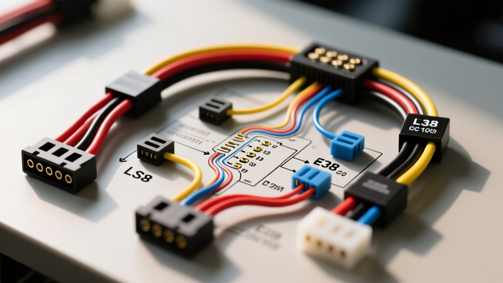
Introduction to the LS3 ECU and Harness Architecture
The GM LS3 6.2L V8 is widely considered the ultimate benchmark for engine swaps, offering a phenomenal blend of reliability, power, and aftermarket support. However, for beginners transitioning from carburetors or older OBD-I systems, the modern Gen IV LS3 wiring harness diagram can look like an intimidating web of fly-by-wire throttle controls, CAN bus networks, and complex sensor arrays. The LS3 utilizes the GM E38 Engine Control Module (ECM), a highly advanced, flash-programmable computer that manages everything from sequential fuel injection to the electronic throttle body.
This beginner-friendly guide breaks down the fundamental architecture of the LS3 wiring harness. By understanding the core power distribution, connector layouts, and critical sensor circuits, you can confidently route, pin, and troubleshoot your harness without relying entirely on expensive standalone plug-and-play systems.
Core Power and Ground Distribution
The most common cause of a no-start condition in an LS3 swap is improper power and ground routing. The E38 ECM requires clean, unswitched battery voltage for memory retention and switched ignition voltage to wake up the fuel and spark maps. According to Helm Incorporated GM Service Manuals, voltage drop across ground circuits is the primary culprit for erratic sensor readings.
| Circuit Type | ECM Connector | Pin Numbers | Wire Color (OEM) | AWG Size |
|---|---|---|---|---|
| Battery+ (Constant 12V) | X1 (Black) | 1, 2, 3 | Red / Red-White | 12 AWG |
| Ignition+ (Switched 12V) | X2 (Gray) | 1, 2 | Pink | 14 AWG |
| Main ECM Ground | X1 (Black) | 41, 42, 43 | Black | 12 AWG |
| Sensor Low Reference | X2 (Gray) | Multiple | Black | 18 AWG |
Pro-Tip for Swappers: Never ground the E38 directly to the engine block or cylinder heads. The block acts as a noisy ground path due to starter motor draw and alternator ripple. Always route the X1 ground pins directly to the vehicle's main firewall ground stud or directly to the negative battery terminal using a dedicated 12 AWG or 10 AWG wire.
Decoding the LS3 Wiring Harness Diagram: Key Connectors
The GM E38 ECM features three primary connectors. Understanding which connector handles which subsystem is the key to reading any LS3 wiring schematic.
X1 Connector (Black, 80-Pin)
The X1 connector is the powerhouse of the harness. It houses the main battery feeds, main grounds, and the high-current driver circuits for the fuel injectors and ignition coils. The injector control wires are typically 18 AWG and utilize a saturated-switch driver topology. The ECM grounds the injector circuit to fire; therefore, the opposite side of the injector pigtail must receive switched 12V from your fuel pump relay or ignition fuse block.
X2 Connector (Gray, 80-Pin)
X2 is the sensory and communication hub. This connector houses the 5-volt reference circuits, sensor signal returns, the Throttle Actuator Control (TAC) module wiring, and the High-Speed GMLAN (CAN Bus) network. If you are integrating the LS3 into a modern chassis or using a digital dash like a Holley Terminator X or Dakota Digital, you will tap into the CAN High and CAN Low wires located here.
X3 Connector (Black, 38-Pin)
The X3 connector handles secondary emissions and auxiliary outputs. This includes the rear (post-catalyst) O2 sensors, EVAP purge solenoid controls, and the primary cooling fan relay grounds. For a basic race or swap application, the X3 connector is often heavily depopulated or entirely omitted to save weight and reduce harness bulk.
Mastering Drive-By-Wire (DBW) Throttle Wiring
The steepest learning curve for beginners tackling an LS3 wiring harness diagram is the electronic throttle body. The LS3 uses a Drive-By-Wire (DBW) system, eliminating the physical cable. The E38 reads the Accelerator Pedal Position Sensor (APPS) and commands the Throttle Actuator Control (TAC) motor.
The APPS pedal connector utilizes 6 pins, relying on redundant circuits for safety. If the E38 detects a mismatch between Signal 1 and Signal 2, it will trigger a reduced-power 'limp mode'. Below is the standard GM APPS pinout:
- Pin A: 5V Reference 1 (Light Blue)
- Pin B: Signal 1 (Dark Blue)
- Pin C: Low Reference 1 (Black)
- Pin D: 5V Reference 2 (Light Blue/White)
- Pin E: Signal 2 (White)
- Pin F: Low Reference 2 (Black/White)
Crucial Warning: Do not attempt to splice or extend the TAC motor wires (which run from the ECU to the throttle body) with standard solder joints or crimp caps. The E38 monitors the inductance and resistance of these 14 AWG motor wires. Poor splices will cause throttle hesitation or immediate limp-mode triggers. If extension is required, use high-quality, shielded, solder-sealed harness extensions.
Essential Engine Sensors and Wire Color Codes
Properly identifying sensor circuits is vital when repairing a damaged harness or verifying pinouts. The SAE J1128 standard for low-tension primary cable dictates the insulation types used in these high-heat environments. Below is a quick-reference table for the most critical LS3 engine bay sensors.
| Sensor | Function | 5V Ref / Power | Signal Wire | Ground / Low Ref |
|---|---|---|---|---|
| Mass Air Flow (MAF) | Measures incoming air mass & IAT | Pink (5V) | Tan (MAF), Yellow (IAT) | Black |
| Manifold Absolute Pressure (MAP) | Reads vacuum/boost load | Pink (5V) | Dark Green | Black |
| Crankshaft Position (CKP) | Engine speed & misfire detection | Yellow (12V) | Dark Blue | Black |
| Camshaft Position (CMP) | Sequential fuel sync | Pink (5V) | Dark Green/White | Black |
Beginner Troubleshooting: Common Harness Mistakes
When your LS3 cranks but refuses to fire, or throws a barrage of U-codes (communication codes), refer to this diagnostic decision tree:
- Security Light Illuminated / No Injectors: The GM Vehicle Anti-Theft System (VATS) is active. The E38 thinks the vehicle is being stolen and has disabled the fuel injectors. Fix: You must use a tuning software (like HP Tuners) to disable the VATS system in the ECM, or install a standalone VATS bypass module that simulates the correct resistor pellet signal.
- U0100 / CAN Bus Codes: The E38 cannot communicate with the transmission control module (TCM) or body control module (BCM). Fix: Verify the High-Speed GMLAN termination. The CAN bus requires a 120-ohm resistor across the CAN High and CAN Low lines. If you deleted the BCM, you may need to install a standalone 120-ohm terminating resistor at the OBD-II diagnostic port.
- Erratic Idle / Stalling: Often caused by a shared 5V reference circuit dropping out. If a sensor like the TPS or MAP shorts internally, it pulls the entire 5V reference bank down to zero. Fix: Unplug sensors one by one with the key ON. If the 5V reference returns to normal when a specific sensor is unplugged, replace that sensor.
Authoritative Resources for GM Gen IV Wiring
To further your knowledge, avoid relying on forum hearsay. Always cross-reference your specific harness year and ECU casting number with factory documentation. We highly recommend consulting the official GM Service Information portal for OEM schematics, as well as resources provided by Holley Performance for aftermarket harness integration and termination best practices. Mastering the LS3 wiring harness diagram is a rite of passage for any modern hot rodder, and with a methodical approach to power, grounds, and sensor signals, your swap will be firing on all eight cylinders in no time.