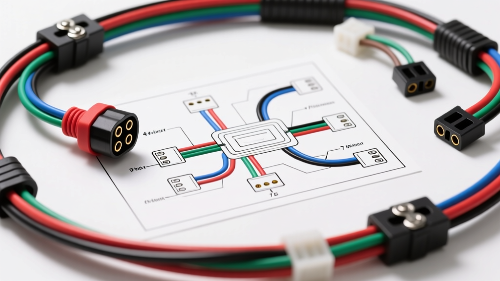
Introduction to Trailer Electrical Diagnostics
When trailer lighting or electric brakes fail, guessing which wire is at fault leads to hours of frustration and potential damage to your tow vehicle's Body Control Module (BCM). A systematic approach using a wiring diagram of trailer harnesses is the only reliable way to isolate faults. Whether you are dealing with a simple 4-way flat connector on a utility trailer or a complex 7-way RV blade connector with proportional brake controllers, understanding the exact pinout, AWG requirements, and circuit logic is critical.
This guide provides a step-by-step troubleshooting flow designed for automotive electrical technicians and advanced DIYers. We will cover source verification, harness continuity, ground integrity, and advanced multiplexed system diagnostics.
Essential Diagnostic Tools
Before consulting the wiring diagram of trailer connectors, gather the proper diagnostic equipment. Relying solely on visual inspection will miss high-resistance corrosion and internal wire fractures.
- Digital Multimeter (DMM): Required for voltage drop testing and continuity checks. A Fluke 115 or equivalent automotive DMM is recommended.
- Incandescent Test Light: Unlike LED test lights, incandescent bulbs draw actual current (typically 50-100mA). This is crucial for testing modern Pulse Width Modulated (PWM) trailer modules, which require a minimum load to activate and stay on.
- Wire Strippers and Crimpers: For repairing damaged circuits.
- Marine-Grade Adhesive Heat Shrink: Standard electrical tape will fail under a trailer's harsh, wet environment. Always use dual-wall, adhesive-lined heat shrink (3:1 shrink ratio) to seal out moisture.
- Dielectric Grease: For sealing connector pins against galvanic corrosion.
Step 1: Isolate the Fault Domain (Vehicle vs. Trailer)
The first rule of trailer diagnostics is to divide the system in half. You must determine if the fault lies in the tow vehicle's output (the receptacle) or the trailer's harness (the plug and wiring).
- Disconnect the trailer from the tow vehicle.
- Turn on the tow vehicle's running lights and hazard flashers.
- Using your DMM or incandescent test light, probe the female receptacle on the tow vehicle according to the standard pinout charts below.
- If the vehicle receptacle outputs the correct 12V-14V on all corresponding pins, the vehicle side is functioning. The fault is isolated to the trailer.
- If the vehicle receptacle lacks power on specific pins, check the tow vehicle's fuses, relays, and factory tow module before touching the trailer harness.
Step 2: Standard Trailer Connector Pinouts & Specifications
Reference these standard wiring diagrams of trailer plugs to identify the correct circuits during your continuity and voltage tests. Note that wire colors are standardized by the RVIA and SAE, but aftermarket or older custom harnesses may deviate. Always trust your multimeter over wire color.
4-Way Flat Connector Specifications
| Pin Position | Function | Standard Wire Color | Min. AWG Size | Diagnostic Notes |
|---|---|---|---|---|
| Pin 1 (Exposed/Ground) | Chassis Ground | White | 14 AWG | Must terminate to bare, unpainted chassis metal. |
| Pin 2 | Tail / Running Lights | Brown | 16 AWG | Check for voltage drop if lights are dim. |
| Pin 3 | Left Turn / Stop | Yellow | 14 AWG | Combined stop/turn on most standard trailers. |
| Pin 4 | Right Turn / Stop | Green | 14 AWG | Combined stop/turn on most standard trailers. |
7-Way RV Blade Connector Specifications
| Clock Position | Function | Standard Wire Color | Min. AWG Size | Diagnostic Notes |
|---|---|---|---|---|
| 1 o'clock | Left Turn / Stop | Yellow | 14 AWG | Verify independent of tail light circuit. |
| 3 o'clock | Reverse Lights / Aux | Red or Black | 14 AWG | Often used for reverse lockout solenoids on surge brakes. |
| 5 o'clock | Chassis Ground | White | 10 AWG | Critical for electric brakes and 12V aux. High current path. |
| 7 o'clock | Right Turn / Stop | Green | 14 AWG | Check for corrosion in the receptacle blade slot. |
| 9 o'clock | Electric Brakes | Blue | 12 AWG | Outputs variable 0-12V DC from the brake controller. |
| 11 o'clock | Tail / Running Lights | Brown / Maroon | 14 AWG | Powers all side markers and license plate lamps. |
| Center Pin | 12V Aux / Battery Charge | Black | 12 AWG | Fused at the vehicle battery. Used for breakaway switches. |
Step 3: Inspect the Trailer Harness and Grounds
If the vehicle receptacle tests good, connect the trailer and move to the trailer side. The most common cause of erratic trailer lighting—such as the right turn signal causing the left tail light to flash—is a floating or high-resistance ground.
The Ground Voltage Drop Test
Do not assume the white ground wire is intact just because it looks connected. Perform a voltage drop test under load:
- Turn on the trailer running lights (Brown wire circuit).
- Set your DMM to DC Volts.
- Place the black probe on a known good ground on the tow vehicle's battery negative terminal.
- Place the red probe on the trailer's main ground ring terminal.
- A reading above 0.1V indicates excessive resistance. Clean the grounding surface with a wire brush, apply dielectric grease, and secure with a star washer.
Expert Insight: Never rely on the trailer hitch ball and coupler as a primary ground path. While it may provide enough continuity to weakly illuminate an LED, it will cause severe voltage drop when electric brakes (drawing up to 15+ amps) are engaged.
Step 4: Symptom-to-Fix Decision Tree
Use this troubleshooting decision tree to rapidly diagnose specific failure modes based on your observations and the wiring diagram of trailer circuits.
Symptom: Tow Vehicle Turn Signals Hyper-Flash When Trailer is Connected
- Cause A: The trailer uses LED lights without integrated load resistors, causing the vehicle's flasher relay to detect a 'blown bulb' (low current draw).
- Fix: Install 6-ohm, 50-watt load resistors in parallel on the yellow and green turn signal wires near the trailer plug.
- Cause B: A short to ground exists on the trailer's turn signal wire, blowing the vehicle's tow module fuse.
- Fix: Check continuity between the yellow/green wires and the white ground wire with the trailer unplugged. Replace damaged harness sections.
Symptom: Brake Controller Displays 'NC' (Not Connected) or 'SH' (Short)
- Cause A (NC): Break in the blue 12 AWG electric brake wire between the 7-way plug and the trailer's brake assemblies.
- Fix: Probe the blue wire at the trailer plug while an assistant presses the brake pedal. If 12V is present at the plug but brakes don't engage, trace the blue wire back to the axle hubs for chafing or severed wires.
- Cause B (SH): The blue brake wire is shorting to the chassis ground, or a brake magnet has failed internally and grounded out.
- Fix: Disconnect the brake magnets at the hubs. Test continuity from the blue wire to the white ground wire. If continuity exists, the short is in the main harness. If not, test each individual brake magnet for internal shorts (should read ~3.2 to 4.0 ohms).
Symptom: Running Lights Work, But Left Turn Signal Stays Solid On
- Cause: A short circuit between the brown (tail) and yellow (left turn) wires inside the trailer harness, often caused by a pinched wire near the tongue jack or axle.
- Fix: Visually inspect the harness where it passes through metal grommets or is clamped to the frame. Separate the wires, repair with solder and adhesive heat shrink, and re-route away from pinch points.
Advanced Diagnostics: Multiplexed Systems & PWM Modules
Modern trucks (such as the Ford F-150, Ram 1500, and Chevrolet Silverado) no longer use simple relay-based trailer circuits. They utilize a dedicated Trailer Tow Module that outputs Pulse Width Modulated (PWM) signals and monitors current draw to protect the vehicle's CAN bus network.
If a short circuit occurs on the trailer, the module will instantly shut down the circuit to prevent a fire. A standard test light may not activate a PWM circuit because the module requires a specific current signature to 'wake up' the output driver. If your test light fails to illuminate on a modern truck, use a DMM to check for a 5V-12V reference pulse, or connect a known-good incandescent trailer light tester to draw the necessary load. If a short has tripped the module, you may need to clear the soft code using an OBD2 scan tool or disconnect the truck's battery for 10 minutes to reset the Trailer Tow Module.
Authoritative References & Standards
For further technical specifications, OEM wiring schematics, and commercial standards, consult the following authoritative resources:
- etrailer.com - Comprehensive Trailer Wiring FAQ and Diagrams: The industry's most detailed visual database for 4-way, 5-way, 6-way, and 7-way connector pinouts and adapter wiring.
- Tekonsha Technical Resources: Manufacturer documentation for proportional brake controller wiring, breakaway switch integration, and PWM module compatibility.
- SAE International - SAE J560 Standard: The definitive engineering standard for heavy-duty commercial 7-way connectors and trailer electrical systems.