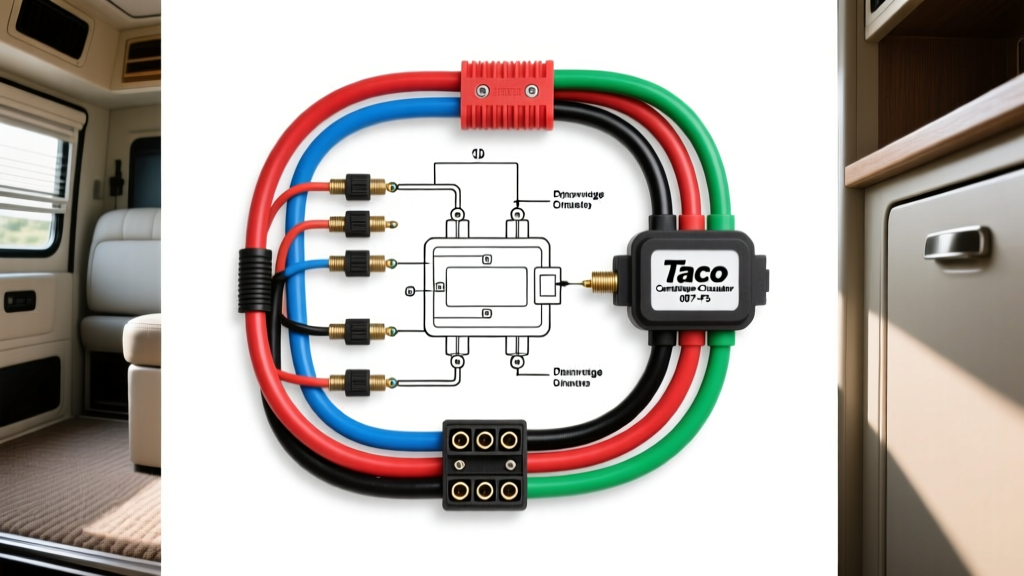
Integrating the Taco 007-F5 in RV and Automotive Hydronic Systems
When adapting residential hydronic components for automotive and recreational vehicle (RV) applications, understanding the crossover between 120V AC alternating current and 12V DC chassis control circuits is critical. The Taco cartridge circulator 007-F5 is frequently utilized in Class A diesel pushers, custom expedition vehicles, and marine vessels to circulate engine coolant through Webasto or Aqua-Hot heat exchangers. Because these vehicles rely on complex inverter systems and DC-to-AC relays to trigger 120V AC components, diagnosing a failure requires a specialized automotive electrical approach. This guide provides the definitive Taco cartridge circulator 007-F5 wiring diagram context for mobile applications, followed by a rigorous step-by-step troubleshooting flow to isolate faults in the power supply, control relay, or pump cartridge.
Taco Cartridge Circulator 007-F5 Wiring Diagram Overview
In a standard motorhome engine pre-heat loop, the 007-F5 does not plug directly into a standard 15A duplex receptacle. Instead, it is hardwired into a dedicated 120V AC circuit protected by a 10A DIN-rail breaker in the coach's main distribution panel. The control side utilizes a 12V DC automotive relay (commonly a 4-pin Bosch-style 30A relay or a solid-state equivalent) triggered by the vehicle's engine pre-heat timer or a snap-disc aquastat. Below is the standard terminal configuration for mobile integration.
| Terminal | Function | RV Wire Color Code | AWG / Type | Torque Spec |
|---|---|---|---|---|
| L1 (Line) | 120V AC Hot | Black (THHN/MTW) | 14 AWG | 12 in-lbs |
| N (Neutral) | 120V AC Return | White (THHN/MTW) | 14 AWG | 12 in-lbs |
| GND | Chassis Ground | Green/Yellow | 14 AWG | 15 in-lbs |
| Control | 12V DC Trigger | Red (SAE J1128) | 16 AWG | N/A (Spade) |
Step-by-Step Troubleshooting Flow
When the Aqua-Hot or engine block heater system calls for circulation, but the Taco 007-F5 remains silent, follow this sequential diagnostic tree. Never bypass the thermal overload protector during testing, as this risks catastrophic stator failure and potential fire in the engine bay.
Phase 1: 120V AC Power & Inverter Verification
Before touching the pump's terminal box, verify that the coach's inverter or shore-power transfer switch is delivering clean AC voltage to the pump's dedicated breaker.
- Set your digital multimeter (DMM) to AC Voltage (V~).
- Probe the load side of the 10A DIN-rail breaker. You should read between 114V and 126V AC.
- If voltage is absent, trace back to the automatic transfer switch (ATS). In RVs, a failed ATS relay will drop the 120V AC leg feeding the hydronic loop.
- If voltage is present at the breaker, proceed to the pump junction box and verify 120V AC across the L1 and N terminals while the system is calling for heat.
Phase 2: 12V DC Control Circuit & Relay Diagnostics
The most common point of failure in automotive hydronic integrations is the 12V DC control relay that switches the 120V AC line.
- Locate the 12V DC relay mounted in the engine bay or utility compartment.
- With the ignition ON and the pre-heat switch engaged, probe the relay's coil terminals (Pins 85 and 86). You must read a minimum of 11.5V DC. If voltage is below 11.0V, the voltage drop across the chassis ground or the 16 AWG SAE J1128 control wire is too high, preventing the relay coil from pulling in.
- Listen for the mechanical click. If the relay clicks but the pump does not run, probe the relay's output terminal (Pin 87) for 120V AC.
- If 120V AC is exiting Pin 87 but the pump is dead, you have an open circuit in the 14 AWG black hot wire between the relay and the Taco terminal block.
Phase 3: Motor Cartridge & Capacitor Testing
If 120V AC is confirmed at the Taco 007-F5 terminal block and the pump still fails to spin, the fault lies within the pump assembly.
- Disconnect all power. Lock out the 10A breaker and disconnect the 12V DC battery negative terminal.
- Remove the 1/4-inch hex screws securing the electrical cover plate.
- Inspect the run capacitor. The 007-F5 utilizes a specific microfarad (µF) rating (typically 2.0 µF or 3.3 µF depending on the exact production run). Set your DMM to capacitance mode. A reading more than 10% outside the rated µF indicates a failed capacitor, which will cause the motor to hum but fail to start.
- Test the internal thermal overload. Set the DMM to continuity (Ohms). Place probes across the overload switch terminals. If the motor recently overheated due to a blocked coolant line or air-locked volute, the thermal switch may be open. Allow the cartridge to cool for 45 minutes and retest.
- Measure the motor winding resistance. Place probes on the L1 and N terminal screws. A healthy 1/25 HP 120V motor should show a resistance between 12 and 18 Ohms. An infinite reading (OL) confirms a burnt stator winding, requiring a complete cartridge replacement.
Quick Diagnostic Decision Tree
- Symptom: Pump hums loudly, shaft does not turn.
- Cause 1: Failed run capacitor. Fix: Replace with exact µF rated capacitor.
- Cause 2: Severe scale buildup binding the ceramic shaft. Fix: Remove cartridge, clean rotor, check volute clearance.
- Symptom: Pump is completely silent, relay clicks.
- Cause 1: Open thermal overload switch. Fix: Reset/cool down, check for air-locked system causing dry running.
- Cause 2: Broken 14 AWG neutral wire. Fix: Perform voltage drop test on the white wire back to the inverter neutral bus.
- Symptom: Pump runs continuously, ignores 12V dashboard switch.
- Cause 1: Welded relay contacts. Fix: Replace Bosch-style relay; check for inductive voltage spike lacking a flyback diode.
- Cause 2: Shorted 12V control wire to a constant 12V source. Fix: Trace 16 AWG red wire for chafed insulation against the exhaust manifold.
Common Installation Mistakes in Motorhome Chassis
Improper grounding is the leading cause of premature capacitor failure and stray voltage corrosion in RV hydronic systems. The Taco 007-F5 must be grounded directly to the vehicle's main chassis ground bus bar using a dedicated 14 AWG green wire with a ring terminal. Do not rely on the mounting bolts to the cast-iron engine block or the Aqua-Hot chassis bracket for the primary AC ground, as engine paint, powder coating, and galvanic corrosion will create high-resistance paths. According to NFPA 1192 (Standard on Recreational Vehicles), all 120V AC appliances must have a dedicated equipment grounding conductor.
Furthermore, when routing the 16 AWG 12V DC trigger wire from the dashboard pre-heat switch to the engine bay relay, ensure the wire is routed away from high-current alternator cables and ignition harnesses. Electromagnetic interference (EMI) can induce phantom voltages in the control wire, causing the relay to chatter and rapidly destroy the Taco 007-F5's internal run capacitor.
Authoritative References
- Taco Comfort Solutions: Cartridge Circulator Installation & Wiring Guides - Official specifications for the 007-F5 terminal block torque settings and capacitor ratings.
- SAE International J1128 - Standard for low-tension primary cable used in the 12V DC automotive control circuits.
- NFPA 1192: Standard on Recreational Vehicles - Guidelines for 120V AC grounding requirements and overcurrent protection in mobile hydronic heating installations.