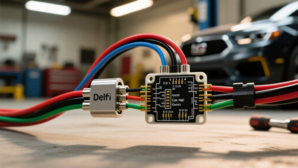
Understanding the LS Gen IV Hall Effect Camshaft Sensor
The transition from Gen III to Gen IV LS architecture introduced critical changes in engine management, most notably the adoption of a 58X crankshaft reluctor and a 1X camshaft position sensor (CMP). Unlike older Variable Reluctance (VR) sensors that output an analog sine wave dependent on engine RPM, the Gen IV CMP is a true Hall effect device. This digital sensor outputs a crisp 0-12V square wave, providing the Powertrain Control Module (PCM) with exact positional data even at cranking speeds. For performance builders and diagnostic technicians, mastering the LS Gen IV cam hall sensor wiring diagram is essential for proper ECU synchronization, especially during engine swaps or custom harness fabrication.
Delphi GT150 3-Way Connector Pinout Specification
The OEM connector for the Gen IV LS cam sensor is the Delphi GT150 3-way female housing (GM P/N 12191518 / ACDelco PT2852). This connector utilizes GT150 female terminals (P/N 12124581) with a secondary lock mechanism and individual silicone wire seals. Below is the definitive pinout and wire color specification based on GM OEM harness routing for the E38 and E67 controllers.
| Pin | Function | OEM Wire Color | Wire Gauge (AWG) | PCM / Source |
|---|---|---|---|---|
| A | Low Reference (Ground) | Black / White Stripe | 20 AWG (0.5mm²) | PCM X2 Pin 5 |
| B | CMP Signal Output | Dark Blue / White Stripe | 20 AWG (0.5mm²) | PCM X1 Pin 20 |
| C | Ignition 1 Voltage (12V Ref) | Pink | 18 AWG (0.8mm²) | Ignition Relay Fuse Block |
Wire Gauge, Insulation, and Shielding Protocols
When fabricating or repairing a hall sensor wiring diagram harness, adhering to OEM wire gauge and shielding specifications is non-negotiable. The signal wire (Pin B) carries a high-frequency digital square wave that is highly susceptible to Electromagnetic Interference (EMI) from ignition coils, alternators, and fuel injectors.
- Signal and Ground (Pins A & B): Must be 20 AWG (0.5mm²). Using thicker wire increases capacitance, which can round off the sharp edges of the square wave at high RPMs, leading to PCM sync loss.
- Power Feed (Pin C): Must be 18 AWG (0.8mm²) to minimize voltage drop over the length of the harness. The Hall IC inside the sensor requires a stable 11.5V to 12.5V supply to operate its internal voltage regulator and Schmitt trigger circuitry.
- Insulation Material: OEM harnesses use Cross-Linked Polyethylene (XLPE) or Tefzel (PTFE) rated for 125°C to 150°C. Standard PVC wire will melt or become brittle in the rear-valley cover environment of an LS engine.
- Shielding: The signal wire must be routed inside a braided copper shield. The shield's drain wire must be grounded at the PCM connector shell only. Grounding the shield at both the sensor and the PCM creates a ground loop, inducing alternator whine and false trigger codes (e.g., P0341).
Terminal Crimping and Connector Assembly Protocols
Proper terminal crimping is critical for maintaining the low-resistance path required by Hall effect circuits. The Delphi GT150 terminals feature a dual-crimp design: a wire crimp and an insulation crimp. Use a Delphi-specific ratcheting crimper to ensure the wire crimp achieves a gas-tight connection. The insulation crimp must grip the Tefzel jacket without piercing it. Before inserting the terminal into the 3-way housing, apply a small amount of dielectric grease (e.g., Nyogel 760G) to the silicone wire seals. This prevents moisture ingress, which is the leading cause of galvanic corrosion on the signal pin, ultimately causing the square wave to degrade into a noisy sine wave.
ECU Integration: GM E38 and E67 PCM Assignments
Gen IV engines (such as the LS2, LS3, L99, and truck variants like the LMG/LY5) utilize the GM E38 or E67 PCM. These controllers process the Hall effect square wave to determine camshaft phasing for Variable Valve Timing (VVT) and sequential fuel injection. When mapping your custom hall sensor wiring diagram to an aftermarket ECU (like a Holley Terminator X or HP EFI), you must configure the input as a "Digital (Hall)" sensor, not a "Magnetic (VR)" sensor. Setting a Hall sensor to VR mode in the ECU software will result in a failure to sync, as the ECU will look for a zero-crossing analog sine wave rather than a digital voltage threshold.
VVT Solenoid Interaction and Phasing Errors
On Gen IV engines equipped with Variable Valve Timing (such as the L99 or VVT truck engines), the PCM relies on the Hall sensor square wave to calculate real-time cam phasing. If the hall sensor wiring diagram is compromised and introduces a 2-millisecond delay in the signal edge, the PCM will interpret this as mechanical timing chain stretch or a failing VVT actuator. This often triggers a false P0011 or P0014 code. Always rule out wiring harness capacitance and ground loop issues before condemning the VVT solenoid or timing chain tensioners.
Oscilloscope Diagnostics: Analyzing the Square Wave
A multimeter is insufficient for diagnosing Hall effect sensor signal integrity. You must use a Digital Storage Oscilloscope (DSO) to visualize the square wave. Connect the DSO probe to the signal wire (Pin B) using a back-probe or piercing probe to maintain harness weatherproofing.
Expected Waveform Parameters
- High State (Voltage): 11.5V to 12.2V (Battery voltage minus internal sensor voltage drop).
- Low State (Voltage): 0.1V to 0.4V (Internal transistor saturation voltage).
- Rise/Fall Time: Less than 10 microseconds (µs). A rise time exceeding 20µs indicates excessive harness capacitance or a failing internal pull-up resistor.
- Duty Cycle: Approximately 50% (varies slightly based on the physical width of the cam reluctor magnet).
If the waveform shows a "shark fin" shape instead of a crisp square edge, the wiring harness is acting as a low-pass filter due to damaged shielding or incorrect wire gauge. If the low state does not drop below 1.0V, there is excessive resistance on the Low Reference circuit (Pin A). Perform a voltage drop test across Pin A to the PCM ground; any reading above 0.1V under load indicates a corroded terminal or compromised splice.
Common Failure Modes and Decision Tree
When troubleshooting a no-start or P0341 (Camshaft Position Sensor Performance) code, follow this diagnostic sequence:
- Verify 12V Reference: Key ON, Engine OFF. Back-probe Pin C. If voltage is below 11.0V, trace the Pink wire back to the ignition relay. Check for blown fuses or high resistance in the bulkhead connector.
- Verify Ground Circuit: Key ON. Back-probe Pin A. Measure voltage to battery positive. Should read battery voltage. If not, the low reference wire is open between the sensor and PCM Connector X2.
- Check Signal Pull-Up: Disconnect the sensor. Key ON. Measure voltage at the harness side of Pin B. The GM E38 PCM does not provide an external pull-up; the pull-up resistor is internal to the Hall sensor IC. Therefore, harness Pin B should read 0V when disconnected. If it reads 5V or 12V, the signal wire is shorted to voltage elsewhere in the harness.
- Inspect Reluctor Air Gap: Gen IV cam sensors are fixed-gap, mounted directly to the front timing cover. If the timing cover is warped or the sensor mounting bolt is over-torqued (spec: 10 Nm / 89 lb-in), the internal Hall IC can crack, causing intermittent signal dropouts at high RPM.
Authoritative Reference Sources
- GM Service Information (SI), Document ID: 2341155 - Camshaft Position Sensor Circuit Description (E38/E67).
- Bosch Automotive Electrics and Automotive Electronics, 5th Edition. Chapter 4: Hall Effect Sensors and Signal Processing.
- SAE International Standard J1939 and J1979 regarding digital sensor EMI shielding and diagnostic trouble code mapping.