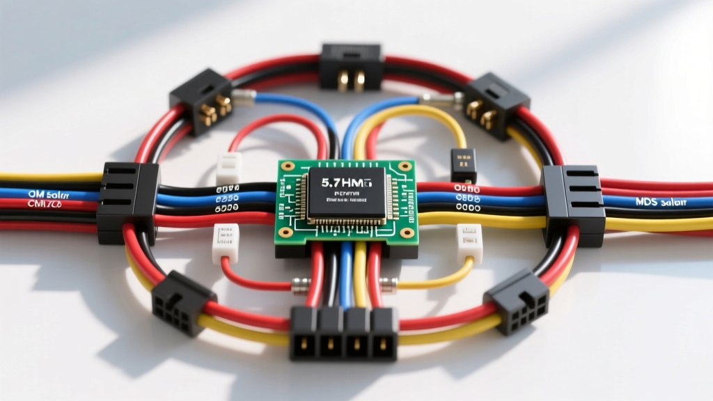
Architectural Overview of the NGC 5.7L HEMI Harness
Understanding the 5.7 Hemi wiring harness diagram requires a deep dive into the Next Generation Controller (NGC) architecture utilized by Chrysler, Dodge, and Jeep. Whether you are diagnosing a factory 2006 Ram 1500, repairing a Grand Cherokee, or building a standalone harness for an engine swap, the electrical topology revolves around a high-speed CAN bus network and a centralized Powertrain Control Module (PCM). The NGC system transitioned from a 4-plug setup in early Gen III models to a more robust 3-plug configuration (NGC4 and NGC5) featuring 38-way Delphi/Molex MX150 connectors. This guide provides an advanced technical deep dive into the PCM pinouts, OEM wire color codes, sensor reference circuits, and Multi-Displacement System (MDS) solenoid routing essential for high-level diagnostics and custom fabrications.
PCM Connector Topology and Pinout Matrix
The NGC PCM utilizes three primary 38-way connectors, color-coded for rapid circuit identification during bench testing or harness fabrication. Proper pin tension and terminal seating are critical; a backed-out pin in the MX150 connector will cause intermittent injector misfires or CAN bus dropouts. Below is the critical pinout matrix for the core power, ground, and communication circuits.
| Connector | Pin | Circuit Function | OEM Wire Color | AWG / Spec |
|---|---|---|---|---|
| C1 (Black) | 2 | CAN C High (PCI Bus) | White (WT) | 20 AWG Twisted Pair |
| C1 (Black) | 3 | CAN C Low (PCI Bus) | White/Black (WT/BK) | 20 AWG Twisted Pair |
| C1 (Black) | 14 | Sensor Ground Bank 1 | Black/Light Blue (BK/LB) | 18 AWG |
| C1 (Black) | 29 | Fused Ignition Run/Start | Red/White (RD/WT) | 14 AWG |
| C2 (Gray) | 1 | Injector 1 Control | Dark Blue/Yellow (DB/YL) | 18 AWG |
| C2 (Gray) | 15 | Coil Pack 1 Control | Dark Green/Orange (DG/OR) | 18 AWG |
| C3 (Green) | 4 | 5V Reference (VREF) | Dark Green/Orange (DG/OR) | 20 AWG Shielded |
| C3 (Green) | 24 | Crankshaft Position Signal | Gray (GY) | 20 AWG Shielded |
Power and Ground Distribution Strategy
The PCM requires three dedicated power feeds and four primary chassis grounds to maintain logic stability during high-load cranking events. The main power relay (ASD Relay) supplies 12V to the injector and coil driver circuits via 14 AWG Red/White wires. Ground straps must be torqued to exactly 10 Nm (89 in-lbs) to the aluminum cylinder heads. Under-torqued grounds introduce variable resistance, which the NGC interprets as false knock sensor activity, resulting in aggressive timing retardation.
Critical Sensor Circuits and 5V Reference Architecture
The 5.7L HEMI relies on a shared 5-volt reference (VREF) circuit for the Manifold Absolute Pressure (MAP), Throttle Position Sensor (TPS), and Accelerator Pedal Position Sensor (APPS). According to FCA TechAuthority service documentation, the VREF circuit is internally protected by a current-limiting diode within the PCM. If a sensor harness chafes and shorts the Dark Green/Orange VREF wire to ground, the PCM will immediately set a P0641 or P0642 code and disable the electronic throttle body (ETC) as a fail-safe measure.
Crankshaft and Camshaft Reluctor Synchronization
Post-2009 'Eagle' 5.7L engines utilize a 58-tooth crankshaft reluctor and a 38-tooth camshaft reluctor. The wiring harness for these sensors must be constructed using 20 AWG shielded twisted pair (STP) cabling. The shield drain wire must be terminated exclusively at the PCM sensor ground (Pin 14 on C1), never at the engine block. Grounding the shield at the block creates a ground loop, introducing electromagnetic interference (EMI) from the high-current ignition coils into the low-voltage Hall-effect sensor signals, leading to P0344 (Camshaft Position Sensor Intermittent) codes.
Multi-Displacement System (MDS) Solenoid Wiring Deep Dive
The MDS system deactivates cylinders 1, 4, 6, and 7 under light-load conditions to improve fuel economy. Electrically, this is managed by four oil control solenoids mounted in the valley cover beneath the intake manifold. The PCM controls these solenoids via Pulse Width Modulation (PWM) on the ground side of the circuit.
- Power Feed: All four MDS solenoids share a common 12V ASD relay feed (Red/White, 18 AWG).
- Control Paths: The PCM provides the ground path via individual 18 AWG wires (e.g., Solenoid 1 is Dark Blue/White, Solenoid 4 is Dark Blue/Yellow).
- Resistance Specification: Each solenoid coil should measure between 10.0 and 14.0 ohms at 68°F (20°C). A reading below 8 ohms indicates an internal short, often caused by oil intrusion past the connector O-ring.
Expert Troubleshooting Tip: The valley cover harness is subjected to extreme thermal cycling and oil vapor. The OEM rubber seals on the MDS connectors frequently degrade, allowing oil to wick up the wire strands via capillary action, eventually contaminating the PCM connector. When repairing an MDS circuit, always cut back the wire at least 6 inches past the connector to remove oil-contaminated copper, and apply dielectric grease to the new Molex terminals.
Common Harness Failure Modes and Diagnostic Decision Tree
When utilizing a 5.7 Hemi wiring harness diagram for diagnostics, technicians must look beyond the schematic and consider physical routing vulnerabilities. Use the following decision tree for common electrical faults:
Symptom: Intermittent Misfire on Cylinders 2 or 7 (P0302 / P0307)
- Check Coil/Injector Pins: Inspect C2 (Gray) connector for terminal fretting corrosion. The NGC connectors are prone to micro-vibration wear.
- Inspect Harness Routing: The rear harness routing near the firewall and exhaust manifolds is notorious for heat degradation. Look for melted loom exposing the Dark Blue injector control wires.
- Verify Impedance: Measure the injector coil resistance. OEM Hemi injectors are high-impedance (approx. 11.5 ohms). If resistance is infinite, the internal winding is open, requiring injector replacement, not harness repair.
Symptom: CAN Bus Communication Dropout (U0100)
- Measure Termination Resistance: With the battery disconnected, measure resistance between CAN C High (Pin 2) and CAN C Low (Pin 3) at the OBD-II DLC. You should read exactly 60 ohms (two 120-ohm terminating resistors in parallel, per SAE J1939 standards).
- Check for Shorts to Ground: If resistance is abnormal, unplug the PCM, TCM, and ABS modules one by one to isolate the short. A common failure point is the harness chafing against the aluminum bellhousing near the starter motor.
Engine Swap and Standalone Harness Integration
Integrating a 5.7L HEMI into a classic muscle car or custom chassis requires careful manipulation of the factory harness. The NGC PCM expects to see a valid CAN bus handshake from the TIPM (Totally Integrated Power Module) and the SKIM (Sentry Key Immobilizer Module) before enabling the ASD relay and injector drivers.
For standalone swaps, fabricators have two primary options:
- BCM/SKIM Bypass Tuning: Retain the factory harness but use custom tuning software to disable the VATS/SKIM security protocols and force the PCM to close the ASD relay internally without CAN bus validation.
- Standalone Harness Fabrication: Strip the harness down to the bare C1, C2, and C3 engine circuits. You must retain the 5V VREF shielded wiring, the dual wideband O2 sensor circuits (which require dedicated 12V heater feeds and separate analog grounds), and the 58X crank sensor shielded pair. Reference Helm Incorporated OEM Service Manuals for the exact pin migration charts when adapting the 5.7L harness to aftermarket standalone ECUs like the Holley Terminator X or MegaSquirt MS3Pro, as the injector firing order mapping (1-8-4-3-6-5-7-2) must be matched to the physical coil pack wiring.
Final Torque and Assembly Specifications
Proper reassembly of the harness and sensors is just as critical as the wiring itself. When reinstalling the PCM connectors, ensure the locking lever is fully seated to engage the secondary terminal lock (STL). The engine block ground straps must be cleaned to bare metal and torqued to 10 Nm. The MAP sensor harness connector should be secured with a zip-tie to the factory bracket to prevent the rigid 18 AWG wires from fatiguing and breaking inside the insulation jacket—a nearly invisible fault that causes erratic fuel trims and stalling at idle.