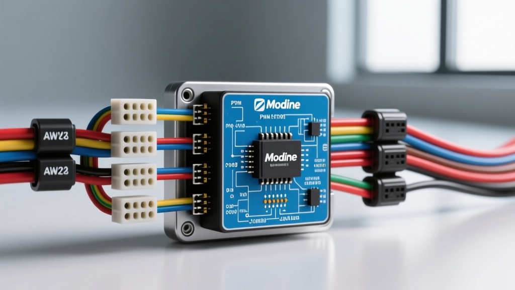
Introduction to Modine Heavy-Duty Heater Architecture
Modine Manufacturing's heavy-duty HVAC systems, specifically the PuraLite and HotDog coolant heater lines, represent a definitive shift from legacy resistor-pack blower controls to advanced Brushless DC (BLDC) motor architectures. For heavy-duty truck technicians, bus fleet maintainers, and RV upfitters, interpreting a modern Modine heater wiring diagram requires a firm grasp of Pulse Width Modulation (PWM) signaling and SAE J1939 CAN bus multiplexing. This advanced technical deep dive dissects the 12-pin main harness connector, power distribution topologies, and diagnostic oscilloscope patterns required to troubleshoot modern Modine cab heaters efficiently.
Main Harness Connector Pinout & Wire Color Codes
The primary interface between the vehicle's electrical system and the Modine heater control module is a 12-pin Deutsch DT12 or AMPSEAL connector. Proper pin identification and wire gauge verification are critical, as undersized power feeds will cause severe voltage drop, leading to BLDC motor controller resets under high-load conditions. Below is the standard OEM pinout configuration for 12V/24V integrated systems.
| Pin | Function | Wire Color (Typical) | AWG / Type | Technical Notes |
|---|---|---|---|---|
| 1 | Main Battery Positive (B+) | Red | 10 AWG TXL | Fused at 40A. Continuous power for logic memory. |
| 2 | Main Battery Ground | Black | 10 AWG TXL | Must terminate to a clean chassis ground. Max 0.1V drop. |
| 3 | Ignition / Enable Signal | White/Red Tracer | 16 AWG GXL | 12V/24V switched. Wakes the HVAC controller. |
| 4 | CAN High (J1939) | Yellow | 18 AWG Twisted | Termination resistor required if end-of-line node. |
| 5 | CAN Low (J1939) | Green | 18 AWG Twisted | Twist rate: 1 twist per inch with CAN High. |
| 6 | PWM Blower Control Signal | Blue | 18 AWG Shielded | 500 Hz square wave from cab thermostat. |
| 7 | PWM Signal Ground | Black/White | 18 AWG Shielded | Dedicated logic ground. Do not splice to Pin 2. |
| 8 | Coolant Pump Enable | Brown | 14 AWG TXL | Drives external Bosch-style 12V auxiliary pump. |
| 9 | High-Limit Thermostat Input | Orange | 18 AWG GXL | Normally Closed (NC). Opens at 190°F to kill fuel/heat. |
| 10 | Fault Code Output (J1587) | Purple | 18 AWG GXL | Legacy serial data for older ECMs. |
| 11 | Reserved / Diagnostic Rx | Gray | 18 AWG GXL | Used with Modine proprietary breakout tools. |
| 12 | Reserved / Diagnostic Tx | Pink | 18 AWG GXL | Used with Modine proprietary breakout tools. |
PWM Blower Motor Control Circuit Analysis
Unlike older 3-speed resistor networks that waste electrical energy as parasitic heat, the Modine BLDC blower module utilizes a 500 Hz Pulse Width Modulation (PWM) signal transmitted from the cab HVAC controller. This signal dictates the duty cycle applied to the internal MOSFETs of the blower motor assembly.
Signal Frequency and Duty Cycle Specifications
- Frequency: 500 Hz (2.0 ms period)
- 0% - 9% Duty Cycle: Blower OFF / Sleep Mode.
- 10% - 14% Duty Cycle: Soft-start initialization sequence.
- 15% - 90% Duty Cycle: Proportional speed control (linear mapping).
- 91% - 100% Duty Cycle: Diagnostic mode / Maximum override.
When diagnosing a blower that only operates at maximum speed, technicians must probe Pin 6 with an oscilloscope. A flat 12V DC line indicates a short-to-power in the harness or a failed HVAC head unit output driver. Conversely, a 0V line with no PWM pulses indicates a broken wire or a failed internal pull-down resistor on the Modine control board.
J1939 CAN Bus Integration & Multiplexing
Modern Modine units act as an active node on the vehicle's SAE J1939 datalink. The heater module broadcasts critical operational data, including coolant inlet/outlet temperatures, combustion fan RPM, and internal fault codes. According to SAE J1939 standards, the Modine controller typically utilizes Parameter Group Number (PGN) 65213 for cab temperature telemetry and PGN 61444 for auxiliary heater status.
Termination and Topology: The CAN bus requires exactly two 120-ohm termination resistors placed at the physical ends of the datalink backbone. If the Modine heater is installed as an end-node on a spur line, its internal 120-ohm resistor must be enabled via a physical jumper on the control board or configured via diagnostic software. An improper termination resulting in 40-ohm or infinite-ohm readings across Pins 4 and 5 will cause intermittent communication dropouts, often manifesting as an HVAC controller displaying a '---' temperature reading.
Advanced Troubleshooting: Voltage Drop & Oscilloscope Diagnostics
Relying on static multimeter readings is insufficient for diagnosing Modine heater electrical faults. The high inrush current of the BLDC motor and the high-frequency switching of the CAN bus demand dynamic testing methodologies.
Decision Tree: Blower Motor Inoperative
- Verify Power Integrity: Perform a dynamic voltage drop test on Pin 1 (B+) and Pin 2 (Ground) while the system is commanded to maximum heat. A combined voltage drop exceeding 0.5V on the 10 AWG TXL feeds indicates corroded bulkhead connectors or undersized aftermarket wiring. Reference the Technology & Maintenance Council (TMC) Recommended Practice RP-158 for heavy-duty voltage drop limits.
- Check Enable Signal: Verify Pin 3 receives full system voltage (within 0.2V of battery positive) when the ignition is ON. If voltage is present but the module remains asleep, proceed to CAN bus verification.
- CAN Bus Oscilloscope Test: Connect Channel A to Pin 4 (CAN_H) and Channel B to Pin 5 (CAN_L). Trigger on the falling edge of CAN_H. The differential signal should exhibit clean, square dominant and recessive states with minimal ringing. Excessive ringing indicates poor shielding or a missing termination resistor.
- PWM Signal Verification: Back-probe Pin 6. If the HVAC controller is outputting a clean 500 Hz PWM signal but the blower remains dead, the internal BLDC commutator board or hall-effect sensors have failed, requiring complete blower assembly replacement.
Installation & Routing Specifications
When repairing or extending a Modine heater harness, strict adherence to automotive wire routing standards is mandatory. All power circuits (Pins 1, 2, 8) must utilize cross-linked polyethylene (TXL or GXL) wire rated for 125°C to 150°C, as heater compartments routinely exceed 100°C ambient temperatures. Standard PVC wire (THHN) will melt and short against the chassis.
Furthermore, the shielded PWM cable (Pins 6 and 7) must have its drain wire grounded at the HVAC controller end only, preventing ground loops that can induce electromagnetic interference (EMI) from the alternator or ignition system. For connector mating, always apply a dielectric grease (such as Nyogel 760G) to the Deutsch DT pins to prevent fretting corrosion, which is a leading cause of high-resistance CAN bus faults in heavy-duty vocational trucks.
References & Industry Standards
- SAE International. (2023). SAE J1939: Serial Control and Communications Heavy Duty Vehicle Network. SAE Standards.
- Technology & Maintenance Council (TMC). (2021). RP-158: Voltage Drop Testing for Heavy Duty Vehicles. American Trucking Associations.
- Modine Manufacturing Company. (2022). PuraLite & HotDog Heavy Duty Heater Service & Installation Manual. Modine HVAC Resources.